This thread has been locked.

If you have a related question, please click the "Ask a related question" button in the top right corner. The newly created question will be automatically linked to this question.

TPS23758: 40Hz Oscillation on Output, IC Fails After Some Time

Part Number: TPS23758
Other Parts Discussed in Thread: , TPS23755

Hello - 

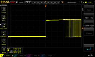
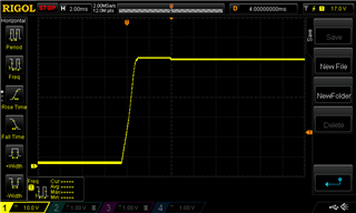
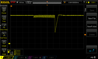
I'm working on a PoE design for a customer and have come up with the attached schematic. When the PoE source is plugged into this design the output voltage from the transformer appears to go to 5V for 10ms before coming down to closer to 2.5V for an additional 10ms. This odd, 40Hz oscillatory behavior appears to happen continuously. Please see the picture and schematic attached.

During the investigation steps for this problem, I disconnected the PoE source from the device and when I tried to plug it back in I didn't see any output voltage from the transformer. The TPS23758 was hot to the touch and I am now measuring approximately 25Ω from VPD to RTN of this board (i.e. across C31 and C32).  

When I measure the voltage across C31 and C32 in this "shorted" state, I see that the voltage is approximately 1.3V.

Given the supply chain shortages I am nervous to replace the IC and test again.  Are there any recommendations or immediate issues that are seen with this design?

Thank you in advance.

-Shane

   TPS23758.pdf

  • I lifted pin 3 of the output transformer and used that to help determine the location of the 25Ω short from VPD to RTN. Instead of the short being on VPD to RTN, the short is actually from DRAIN to RTN. This suggests that the internal switching FET from DRAIN to RSNS has failed in a short circuit.  VPD to RTN in this scenario has a high impedance. 

    The switching frequency as set by Rfrs (68kΩ in my schematic) is approximately 220.5kHz.  This is slightly lower than the 223kHz minimum switching frequency as dictated by the datasheet.  Is this causing this problem?

    When the PoE source is applied to the device, the voltage at VPD (labelled VPOS) is only capable of getting up to approximately 3V which is almost certainly caused by the internal short from DRAIN to RTN.  Notice that there is some kind of switching that occurs on the rail at approximately 50Hz.


    The voltage from DRAIN to RTN is practically the same since the two nodes are tied through the primary transformer winding.

    The voltage from VCC to RTN is trying to regulate, but it is not able to get much higher than 2.5V.

    With the DRAIN pin of the transformer lifted, the voltage presented by the PoE source seems to go directly from 0V to approximately 50V seemingly without any detection sequence.  It holds that voltage for approximately 400ms before returning to GND and then starting again after approximately 2 seconds. 


    In this state the voltage from VB to RTN is also acting very oddly. It regulates to approximately 5V as expected, but it oscillates for 250ms before sharply dropping to approximately 2V every 1.5ms.


    What caused the DRAIN FET to short out and what caused the output to oscillate in the way shown in the original post?

  • I replaced C26 (the capacitor from VCC to RTN) with a 10uF, 25V, 0603 capacitor. The datasheet for the TPS23758 has differing information about how much capacitance to put on that pin from 1uF, 3.3uF, to 22uF. 10uF seems like a safe bet.

    I replaced the resistance of Rfrs (R23) to 59kΩ to change the switching frequency of the device closer to the recommended 250kHz.

    I also changed the Rsns resistor (R24) to 0.5Ω to match the recommended EVM schematics.

    I noticed that the dot notation of the transformer's primary winding did not match the windings indicated by the EVM and in the datasheet. All of the various EVM and reference schematics for the TPS23758 have VPD connected to the primary winding on the side with the dot notation, CP connected to the primary aux winding on the side with the dot, and the 5V output from the transformer connected to the side opposite to the dot notation. Some schematics have that flipped with VPD connected opposite the dot, CP connected opposite the dot, and 5V connected to the dot.  This is different than my schematic where VPD and 5V are connected to the dot and CP is connected opposite to the dot.

    I lifted the pads of the primary winding for the transformer (pins 3 and 4) and swapped the locations that they were soldered to such that the VPD net is connected to the side opposite to the dot notation and powered the board up with a new, unused TPS23758 soldered in place.

    The voltage measured at the net labelled 5V_PoE was being regulated up to approximately 6.2V as opposed to 5V which was likely due to the crude regulation that the Zener diode, D11, was providing. The same odd cycling of the output voltage was no longer being seen, but this is still not good behavior.  After disconnecting the PoE source device and reconnecting it moments later the same short from DRAIN to RTN occurred which prevented any further operation. 

    This tells me that the transformer was generating an output voltage significantly larger than the expected 5V output.

    The TPS23758 died again in this scenario, so there are clearly more issues happening.  Any ideas? Recommendations?

  • Does anyone have any suggestions for this issue?  This is mission critical at the moment and is blocking future development.

  • Hello, 

    Thanks for your post. 

    First, the TPS23758 is not intended to be used in a PSR diode flyback. This will lead to poor regulation which is part of what you are seeing. The other issue is PSR requires a specific transformer construction method and implementation. We here at TI designed them, so we know which vendors we have given the recipe to, and this is not one of them. So this design will not work. 

    Connecting the pins for the auxiliary winding will certainly create damage in the IC. The other reasons the DRAIN will break is from either over voltage (150V) or over current. I would suspect overcurrent here. However, I strongly suggest starting the design over by switching topologies to a synchronous flyback. Please use the EVM as the basis for the design. Thanks. 

    If this post answers your question, please indicate so by marking this thread as resolved. Thank you.


    Regards, 


    Michael P.

    Applications Engineer

    Texas Instruments 

  • Hi Michael -

    Thank you for your response.  We were referencing a schematic for the 'PoE Featherwing' shown here: https://cdn.hackaday.io/files/1683567202943104/PoE-FeatherWing-2.pdf which is behaving correctly with a PSR flyback diode. Is it that the TPS23758 won't work at all in this configuration or that it isn't recommended? I wouldn't expect the PoE Featherwing to work at all if it was not meant to be built in this way at all.

    The TPS23758EVM-080 evaluation board lists out two transformers: Linkcom Manufacturing Co. LDT1018-50R and Wurth Elektronik 750318525. Are these the only two that work with this IC? If the construction of the transformer is critical then that should be listed in the datasheet for the part but I have not been able to find any sections that suggest that.   The PoE Featherwing utilizes the HanRun HR051067, is this a part that was designed by TI and available for use with this IC?

    Thank you again for this input, it is extremely helpful. 

    -Shane

  • Hey Shane, 

    The product title includes the topology: 

    Additionally it is mentioned on the first page 

    The TPS23755 is the sister part of the TPS23758 that is intended for PSR diode flybacks, if you are interested. 

    To clarify, it may work but the efficiency and load regulation is not going to be in the 1% accuracy range we spec in the datasheet. If the design can accept a wider range than 1%, then maybe it would work for this design. We did not test diode flybacks because we made the TPS23755 for diode flybacks. So the design can operate and show an output voltage, but I would not consider it a robust solution. 

    For the transformers, these are the only two that we have designed and approved for primary side regulation (PSR) in a synchronous flyback for 5V. We do not include this in our datasheet since this is a specific application and our part has multiple applications. For example, this transformer would not work in a buck or a 3.3V flyback. Additionally, the part can be used in a design that uses optocoupler feedback instead of PSR, so then many more transformers could be used. So we do not include this information in our datasheet. 

    We do point this out in our PoE PD Schematic Review Guidelines

    If this post answers your question, please indicate so by marking this thread as resolved. Thank you.


    Regards, 


    Michael P.

    Applications Engineer

    Texas Instruments 

    If this post answers your question, please indicate so by marking this thread as resolved. Thank you.


    Regards, 


    Michael P.

    Applications Engineer

    Texas Instruments 

  • Hi Michael -

    Thank you again for the detailed response. We'll probably chalk this up to referencing alternative schematics outside of the TI specified EVM.  That was where the confusion came from with regards to a PSR diode flyback topology and using the TPS23758.

    I've marked your answer as being our solution, but I may either open a separate question or reply here if additional items come up. 

    We will likely try out the transformer that the PoE Featherwing utilizes while simultaneously spinning off a revision to our existing design that incorporates the  synchronous flyback topology for 5V regulation in the same way that the EVM for this part does.

    Is TI able to perform a schematic sanity check for this updated design when it is complete?

    -Shane 

  • Hi Michael -

    We've updated the design around the TPS23758 to more closely match the EVM for that part.  Will you please review this quickly and let me know if there are any concerning items that should be addressed? I'm primarily curious about whether or not the pinout for the transformer is correct. I believe it is, but I need confirmation as there isn't any information in either datasheet (the IC or Xfmr) that indicates how to properly hook it up.

    We are also stepping through the Schematic guidelines document that you had linked, but your eyes would be very useful.

    Thank you in advance.

    -Shane

    7026.TPS23758.pdf

  • Hey Shane, 

    I can have it reviewed by the End of the Week. 

    The transformer polarity is correct in the EVM schematic. You can use this for reference, and you could also order an EVM for performance comparisons. Thank you. 

    If this post answers your question, please indicate so by marking this thread as resolved. Thank you.


    Regards, 


    Michael P.

    Applications Engineer

    Texas Instruments 

  • Comments in Private messenger: 

    If this post answers your question, please indicate so by marking this thread as resolved. Thank you.


    Regards, 


    Michael P.

    Applications Engineer

    Texas Instruments