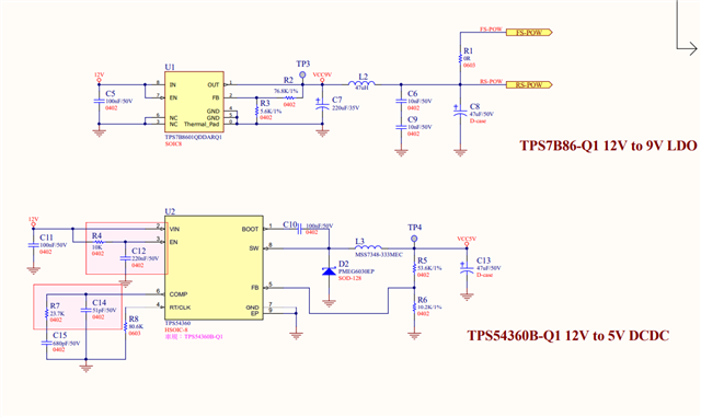
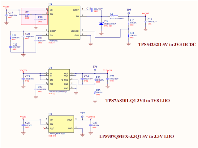
Hi Team,
There is a good new that we DIN TPS54360
And there have one thing need your support!
Please help check this SCH, THX

This thread has been locked.
If you have a related question, please click the "Ask a related question" button in the top right corner. The newly created question will be automatically linked to this question.
Hi Team,
There is a good new that we DIN TPS54360
And there have one thing need your support!
Please help check this SCH, THX

Hi Frank
After discuss with customer , we have updated SCH & refer to attachment (L=33uH datasheet )!
And Io= 3A
1.Please help check this SCH, THX
2.2.Cause this case need design power sequence , how could I design & calculate THX

Hello Kygo,
1. Comments on the schematic:
a. The input capacitor is only 100nF. This seems very low. The datasheet has 2x2.2uF as an example. Webench recommends 4.7uF.
b. The compensation component values and output capacitor value are close to what Webench recommends for this design. However, the inductor should be in the 3.3uH range. The part number mentioned in the schematic is MSS7348-333 which is 33uH. This will result in low phase margin with the existing compensation. Please recommend staying with 3.3uH.
2. In terms of sequencing and simulating - you can use webench or run a PSpice for TI.
Regards,
Denislav
Hi Denislav
Thank you for your feedback!
May I use R4 & C12 to be a RC delay ?
And the power sequence as below for your reference,THX


Hi Kygo,
I don't see an issue with RC delay on the EN pin, but one thing to note is the abs max rating on EN.
You should have a divider to bring the applied voltage on EN below abs max.
Please see the datasheet section on "7.3.7 Enable and Adjusting Undervoltage Lockout".
Regards,
Denislav
Hi Denislav
Thank you!
I'm calculating the startup time, can you help me confirm whether my calculation is correct?
TPS54360 after get 12V then will need 2.62mS(0.42mS + 2.2mS) to give Vcc5V
(T=R*C=R4*C12=2.2mS)

Hello Kygo,
The built in soft start time depends on the switching frequency:

I wanted to highlight again that the abs max rating on EN is 8.4V. You should use a resistor divider from VIN to reduce the final applied voltage on EN below the abs max.
I think 100k top R, 20k bottom R, and 0.1uF Capacitor on EN should work. It would add about ~1.8ms delay to enable and then the soft start will add another ~0.8ms. I assume you want to get the 5V rail in 2.6ms and the soft start time is included in this duration.
Here is a calculator with these estimates.
Standard disclaimer applies: https://www.ti.com/legal/important-notice-and-disclaimer.html
Regards,
Denislav
Hi Denislav
Thank s for your remind!!!
I will take care "Important Notice and Disclaimer"
And I will discuss with RD for change " 100k top R, 20k bottom R, and 0.1uF Capacitor on EN "