This thread has been locked.

If you have a related question, please click the "Ask a related question" button in the top right corner. The newly created question will be automatically linked to this question.

BQ76PL455A-Q1: How to Reading bFrame in example code?

Part Number: BQ76PL455A-Q1
Other Parts Discussed in Thread: BQ76PL455EVM,

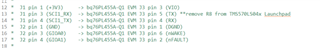
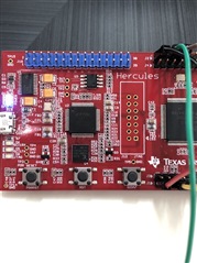
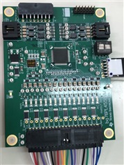
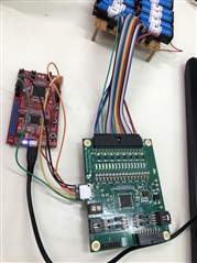
I am trying to program the TMS57004 Launchpad with the sample code provided by TI to work with the BQ76PL455EVM.

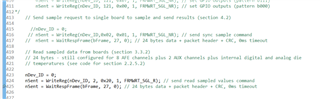
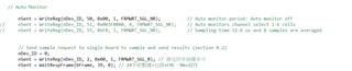
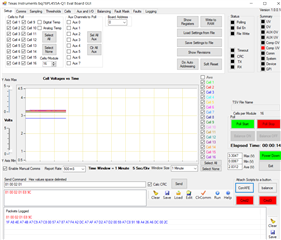
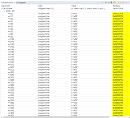
I set the bFrame in the watch window but almost value is 0.I need to watch the battery voltage in the bFrame format is sixteen bits.

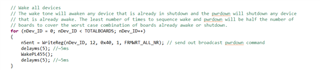
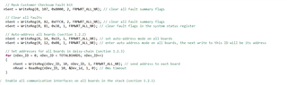
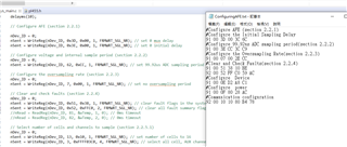
I set the read command and set the Interrupt to the bFrame 

  • Kuanlei,

    bframe is the array which holds the read back data. If it is all zeros, either the read back data is all zeroes or the device is not responding because it is not awake or was properly addressed first. Were you able to first wakeup and address the device and read back any basic info yet? Otherwise please check if the device is awake and the LDOs are up properly according to the datasheet. Another thing is to double check if your mcu connections are correctly placed on RX/TX etc.

    Regards,

    Taylor

  • Could you teach me a simple way to test the BQPL455EVM whether it is waked ?

    I follow the example code title remove the R8 from the TMS570432 Launchpad and jump wires to connect the devices.

    and this is my hardware set TMS5704x(remove R8),and EVM SW2 & SW1 set in picture, Is it correct?

    when I try the balances function it can work !

    so I think it will be wake.

    but I can't get the voltages  please help me.

  • Do you have a simple code can test wake the BQPL455EVM and address the device and read back any basic response?

    This is my code 

    1.WAKE

    2.ADDRESS

    3.Configure AFE 

    4.Select number of cells and channels to sample

    5.Auto monitor off

      And  Send sample request to single board to sample and send results

    bFrame array values almost is 0.

  • This is my balancing mode.

    the balance LED is light on the EVM .

  • This is wake signal.

    when I not resume the CCS code the wake pin(EVM pin6) voltage is 12.2mv.

    However I resume the code the wake pin(EVM pin6) voltage is 3.1v.

  • This is my RX pin (EVM PIN5) signal in the scope.

  • Hi Kuanlei,

    Wakeup pulse should be 0-1-0 so why does it measure 3V after sending it?

    Also I cannot tell what voltage RX is at in this picture. Can you show it when you attempt to communicate to see if any data is flowing?

    Also do you only intend to balance the bottom channels or why do you only have the bottom ones LED light up?

    Regards,

    Taylor

  • Hi Taylor Vogt,

    Thank for your reply!

    I find the thread https://e2e.ti.com/support/power-management-group/power-management/f/power-management-forum/573654/ccs-bq76pl455evm-sample-code-for-tms57004-and-bq76pl455evm-not-working 

    The engineer show the picture in thread,and his nWake signal like my video signal, isn't it ?

    The RX voltage is 4.26V

    I don't know how to show the data,this is my main question.

    Could you teach me how to do?

    I not only to balance the bottom channels,I want balance all channel but when I modify the code as follows.

    I modify the 0x06 ->0x10 (6->16 cells), but it didn't work. I don't know how to balance all battery.

    It just simple test the TMS570 can communication BQPL455EVM.(If balance LED light is mean success.)

    nDev_ID = 0; 
    // nSent = WriteReg(nDev_ID, 13, 0x06, 1, FRMWRT_SGL_NR); // NCHAN : set number of cells to 6.

    nSent = WriteReg(nDev_ID, 13, 0x10, 1, FRMWRT_SGL_NR); // NCHAN : set number of cells to 16.
    nSent = WriteReg(nDev_ID, 3, 0x000600C0, 4, FRMWRT_SGL_NR); // select all cell, AUX channels 0 and 1, and internal digital die and internal analog die temperatures

  • Hi Kuanlei,

    Are you able to try with our GUI first just to ensure you can check everything in the setup is working? It is difficult to follow what is working so far, so having a clean setup to compare against might be helpful.

    Regards,

    Taylor

  • Hi Taylor Vogt,

    OK , that me show you some video and picture.

    This is the wakeup signals in the scope,just like you say Wakeup pulse should be 0-1-0 

    This is the RX/TX signals in the scope.

    yellow:RX

    blue:TX

    This is use "Software Design Reference" document

    4.2 Method 1: Detailed Steps for Reading Voltages from Single Board in Daisy-Chain Network .

    in the GUI it can work normally,and easy to operation.

    when I command in the GUI  BQ76PL455 can response data for me.

    how could I do when I use the TMS570432 with bq76pl455.?

    After you read my question, is there something wrong with the wakeup?

    I check the code in the CCS,the wakeup command as follow picture.

    Is the TOTALBOARDS should be set 1 ? 

    Because I just only one board.

  • Hi Kuanlei,

    Ok does the wakeup command look the same from the GUI as from the MCU? Can you find any differences?

    Yes TOTALBOARDs should be 1. Could perhaps RX and TX be swapped on the MCU connections? Or some other misconnection?

    Did you change any of the example code or leave as is? Try not changing the code first.

    Also did you try removing R8 and R9 from the MCU as below:

    Regards,

    Taylor

  • Hi Taylor Vogt,

    I'm already remove R8 & R9 

    and I have a question 

    when I set the same commend(Configure AFE (section 2.2.1))  in the GUI with CCS example code (NOT CHANGE CODE)

    The battery voltage will become 0V.

    Where should I need modify the Configure AFE ? 

    I already refer to bq76PL455A-Q1 Software Design Reference