This thread has been locked.

If you have a related question, please click the "Ask a related question" button in the top right corner. The newly created question will be automatically linked to this question.

TPS40057: TPS40057

Part Number: TPS40057
Other Parts Discussed in Thread: LM25145, LM61460

Hello, I am using TPS40057 buck converter for supplying 5V-5A with input supply of 24V. However, on different circuit I am testing the output voltage ranges between 3V to 5.5V.

For values of passive components I referred a ready made circuit from local market which supplies proper output voltage of 5V-5A.

I am attaching the circuit schematic.

Kindly provide some guidance regarding the issue being faced.

  • Hi Samrudha,

    Check C237 from COMP to FB as 6.8nF seems very high (this should set a high-frequency pole at Fsw/2). In general, check stability via simulation knowing the ESR of the 220uF output electrolytic.

    The LM25145 is our recommended controller for such applications. Also, you might consider the LM61460 36V/6A converter for an easier-to-design solution with smaller size.

    Regards,

    Tim

  • Hi Timothy,

    I was able to get 5V-5A output on one of the circuits. However its was just 1 out of 5 circuits.

    The other 4 are still giving same output voltage of 3.8V to 4.1V.

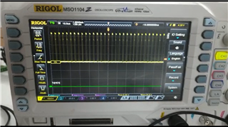
    On further checking I found out that the output voltage is getting switched-on and off continuously. Below is the attached waveform.

    The gate pin of mosfet switches on and off continuously as well. Below is attached image of its waveform.

    Reason I am not using other IC is that they are not available currently and suggested date of availability is in 2022.

    Kindly suggest further modifications required.

  • Hi Samrudha,

    The gate pin is switching as expected at the desired switching frequency (looks like ~300kHz in the plot above).

    Please check stability on the good board by taking a load transient (e.g. 2.5A to 5A).

    Regards,

    Tim

  • Hi Timothy,
    Regarding TPS40057 discussion, after checking the datasheet, I noticed that capacitors C262, C263 and resistor R257 mentioned in above shared schematic were not implemented in datasheet.
    After removing those components and adjusting values of R259 and R260, I got 5V output voltage.
    However the schematic (on page 5) in application note mentioned below, those capacitors and resistor are used (C12,R10,C13).

    www.ti.com/.../sluu190.pdf

    Kindly clarify the significance of using those resistor and capacitors before and after inductor, and whether I should keep them in my circuit or go further without using them.

  • Hi Samrudha,

    R257 and C262 (4.7 Ω and 2.2nF) is a snubber network used to limit the dv/dt and overshoot of the SW voltage. 2.2nF is a very high value and causes high snubber resistor loss. This snubber may not be required depending on the SW voltage overshoot (this depends a lot on layout and component placement, particularly in terms of keeping the input cap close to the IC).

    C263 at 10uF looks like an output cap. It should not go from VOUT to FB.

    Regards,

    Tim