This thread has been locked.

If you have a related question, please click the "Ask a related question" button in the top right corner. The newly created question will be automatically linked to this question.

TPS2121: Power path controller between Li-ion battery and USB-C adapter 5V 3A

Part Number: TPS2121

20211129_Main Board_Power Path Controller.pdf

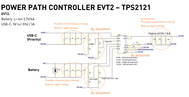
The team I am managing has developed a circuit with as input a USB-C adapter 5V(+/- 5%) 3A (priority) and a Lithium-ion battery 3,7V 4A. The PCBA has been produced and currently being tested with its load (LEDs, vibration motors, RF board). When starting the device with USB-C and battery connected, the device gives priority to the battery and not the USB-C. What could be the reason?

Additionally if only powered by USB-C the device does not manage to pass the self-test. The input voltage of the power path controller measured in that case is over or under the 4,75-5,25V at certain times.

Attached is:
1) a schematic: on the PDF one can click on the components for more details
2) An image of the schematics with note of USB-C input and battery input
3) Measurement of the voltage when the device is power on USB-C only during self test

Thank you in advance for support.

  • Hello Maeva,

    Was the output enabled at any point during the USB-C only test? Typically when connecting to the load the supply voltage drops slightly; however, it seems to keep increasing (low res so it's difficult to say for sure but significantly increases). Is this supply connected through long cables and hot plugged?

    Can you please provide scope shots of the initial test (Both inputs high) with PR1, CP2, Vout and ST included? With PR1 and CP2 set as it says in the schematic it should prioritize IN1. If it doesn't it's likely due to a unstable supply. This device responds to the inputs it's given, so if the input keeps falling/rising significantly when the load is connected/disconnected then it's possible you'll see unexpected behavior. 

    Could you also provide your resistor divider values for PR1/CP2/OV1/OV2?

    Regards,

    Kalin Burnside

  • Dear Kalin,

    Thank you for your feedback. I forwarded it to our engineer and he provided the attach PDF with all detailed information.

    Please let me know if anything else would be required.

    Best,
    Maeva Schaller

    20211130_TI Power Path Controller Design_WL.pdf

  • Hello Maeva,

    According to your schematic PR1 is connected through IN1 via resistor divider network, yet PR1 is somehow high before a voltage is supplied to IN1. The same thing occurs with IN2 and CP2. Can you explain this since this shouldn't be possible? Also, it's important to show the ST pin signal in good resolution during events such as the solo USB-C test.

    Regards,

    Kalin Burnside

  • Hi Kalin,

    I checked with our engineer and he provided the below explanation of the process of doing the measurement.

    Our oscilloscope uses channel 1 as the trigger signal to let the oscilloscope measure the waveform. The test steps are:

    1. Connect the oscilloscope probe to the equipment test point.
    2. Connect the USB-C adapter to the device.
    3. Connect the oscilloscope channel 1 probe to the device.

    But on why the signal is at a high level before triggering, he can't explain. He tested it several times and it always behaves in this manner.

    We are processing more measurement, I will send more info tomorrow.

    Best,
    Maeva Schaller

  • Hello Maeva,

    Have you been able to procure the measurements?

    Regards,

    Kalin Burnside