This thread has been locked.

If you have a related question, please click the "Ask a related question" button in the top right corner. The newly created question will be automatically linked to this question.

BQ76952EVM: Programming TI Eval board (BQ76952EVM) for making SPI communication compatible (where BQ76952 is default I2C)

Part Number: BQ76952EVM
Other Parts Discussed in Thread: BQ76952, BQSTUDIO

Dears,

 As per the given data sheet we followed the programming steps in TI Eval board (BQ76952EVM) for SPI communication establishment (default I2C).

But still we do not established SPI communication interface in BQ76952 (Default I2C).

Attached doc  shows steps followed for SPI communication establishment.

Thanks and regardsDefault I2C to SPI communication establishment.pdf

Subhash Dhyani

  • Hi Subhash,

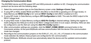
    I think you are missing an important step - there is a level translator on the EVM that is referenced to the REG1 regulator voltage. If REG1 is not enabled, the EVM will not be able to communicate with BQStudio. You can see the level translator in the EVM Schematic shown in the EVM User Guide. If you have already programmed OTP on the other registers, you can supply 3.3V directly to the REG1 pin on the EVM and restart BQStudio - it should be able to detect the SPI setting and communicate then. 

    The EVM User Guide has a sequence of steps you should follow for switching to SPI (see Changing the Communcation Mode section of the document). 

    Best regards,

    Matt

  • Hi Matt,

    Thanks for your suggestions. We are able to do I2c to SPI communication in TI evaluation module BQ76952EVM).

     But as you know that  power resetting will always put device in I2C-default Mode. 

    During i2C-Default mode to SPI Mode conversion Over I2C lines following steps has been taken. 

    1. Set command for Swapping from i2C-Default to SPI Mode Over I2C Communication.
    2. Swapping done by getting NACK over I2C Line
    3. Now SPI Code should run over SPI Communication line.  

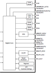
    But unfortunately, this cannot be  done because  we have  hardware limitation (I2C-SDA data line and SPI MISO are same line ,conflicted).  So compiler does not allow it.  

    So as we told that OTP is not an option for us (we are in Design phase  and  field programmable option is kept in our BMS).  So Please suggest us how to go ahead with current hardware and what needs to be changed in our current  hardware to achieve this. As  BQ7695201  (default SPI device) IC is not available in the market and we have only option to run  SPI in BQ76952 (default I2C) device only. 

    Thanks and regrads

    Subhash Dhyani 

  • Hi Subhash,

    Unfortunately our engineering team is out for vacation. We will be getting back to you in the first week of January

  • Hi Subhash,

    Unfortunately, there is no easy way to work around this challenge. This is why the BQ7695201, BQ7695203, and BQ7695204 were created for users who are not able to program the OTP in their production line. Device availability should improve this year, but it is difficult to predict.

    Best regards,

    Matt

  • Hi Matt Sunna,

    Now we have started working on I2C communication based BMS System with BQ76952 device. But here we are unable to go beyond 800Hz I2c communication speed .

     We are using microcontroller  R5F10PGE(F14) from Renesas Electronics. If we go beyond 800Hz then we have below issue.

    1. When we read the cell voltage/temp/current, it is not giving appropriate values ( some time 0X00....sometime 0XFF..etc)
    2. Both master and slave devices are very close but still we used 2K2/4K7 etc as pullups on both the lines. 
    3. During read cycle we have added 100us delay between every BYTE read. This delay has been increased  BYTE by BYTE upto 750uS  but still facing same issue.
    4. We never got NACK during  any read cycle.It means Master Slave communication is proper but  received data is not correct.
    5. Start stop condition are seen  and are OK. we have single master (R5F10PGE(F14)) and single Slave  (BQ76952) system.

    Thanks and regards

    Subhash Dhyani

  • Hi Subhash,

    Is the Comm Type set to I2C Fast mode (this is the default mode for the BQ76952 device, if you are using a SPI device, the Comm Type should be changed to 0x08). I do not know anything about your specific microcontroller, but the device should support clock stretching (see this site for info on I2C clock stretching: https://www.i2c-bus.org/clock-stretching/). 

    The BQ76952 Software Development Guide has many I2C waveforms. Maybe you can compare these to what you are seeing in your system. There are also code examples available for both MSP430 and STM32 microcontrollers available for download.

    Best regards,

    Matt

  • Hi Matt Sunna,

    We are using default I2C AFE device  (BQ76952) now. Here  as said earlier we have a I2C Communications speed issue. We are  unable to communicate above 800Hz.

    • If we run the system in 20KHz we got  NACK in the 9th clock. ON DSO we have seen that there is a delayed response from BQ76952 IC (ACK is delayed). Delay in ACK is considered as NACK by controller.
    • If we increase communication frequency upto 100KHz same delayed response as 20KHz is there . With this we also found that the rise time of clock (SCL)  and  Rise time of data (SDA)  is different but fall time for SCL and SDA are same.

    Please see the attached waveforms.

    Ref I2C Waveforms.pdf

    Thanks and regards

    Subhash Dhyani

  • Hi Subhash,

    Does your microcontroller support clock stretching?

    Matt

  • Hi  Matt, 

    Sorry for late reply.  Yes our hardware have clock stretching.

     We are still fighting for better I2c speed. Just want to know what is the power supply requirement for digital core below.  it required 5V or 3.3V.

    Because your  eval board is running on 3.3V only. So this is recommended/ requirement of MSP430 or AFE BQ76952 (digital core).

    Thanks and regards

    Subhash Dhyani

  • Hi Subhash,

    The power for the digital core is not supplied externally - it is powered from the internal reference. I2C does need an external rail for the pull-up resistors. This can come from the REG1 or REG2 voltages or it can be supplied externally. On the EVM, there is a 3.3V supply because REG1 and REG2 are not powered by default. You should use the voltage of your microcontroller digital pin logic levels for the pull-up voltage. 

    If you are having trouble with the rise times on the I2C signals, you can try using 5k pull-up resistors instead of 10k to see if it helps. 

    Best regards,

    Matt

  • Hi Matt,

    we are using external supply only. Not using internal LDOs

    We have tried with different  pull up resistances 10K/5K/2k2 etc. but  there is no improvement. 

    Please see attached uC data sheet which  we are using in our BMS.  please see below link.

    https://www.renesas.com/eu/en/document/mah/rl78f13-f14-users-manual-hardware-rev210

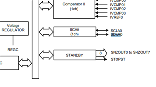
    Here we are using dedicated i2c ports as SCLA0 and SDAA0.

    Please support if you can help to run I2c. The problem as discuss earlier is not getting correct data above 800Hz.

    Thanks and regards

    Subhash Dhyani

  • Hi Subhash,

    I do not have the specific uC you are using, so I cannot test this out for you. I suspect your issues are coming from your uC. It can be challenging to set up a uC for correct I2C communication, so I suggest you check forums from the uC manufacturer for tutorials and hints to help debug.

    Regards,

    Matt

  • Hi Matt,

    Thanks for your suggestion. Issue has been solved  by putting I2c line in another I2c port having clock stretching features.

    thanks and regards

    Subhash Dhyani