This thread has been locked.

If you have a related question, please click the "Ask a related question" button in the top right corner. The newly created question will be automatically linked to this question.

TPS51285B: A short circuit testing in the USB-A port results the 5V system power dropout

Part Number: TPS51285B

Hi Sir,

Our customer reported that when they are doing the short-circuited testing (Vbus and GND short-circuited) with USB-A interface, that will cause the 5V system power dropout and then the main board to shut down. There is no such problem when using other 5V DC/DC power supply schemes.

1)There is a SW current limiting switch in the USB-A port, the schematic is as follows:

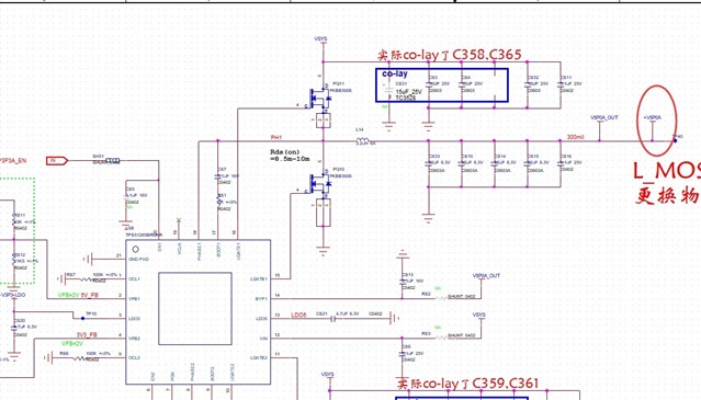
2) The input source of the SW current limiting switch comes from the +V5P0A power supply of the TPS51285B control output, the schematic is as belows:

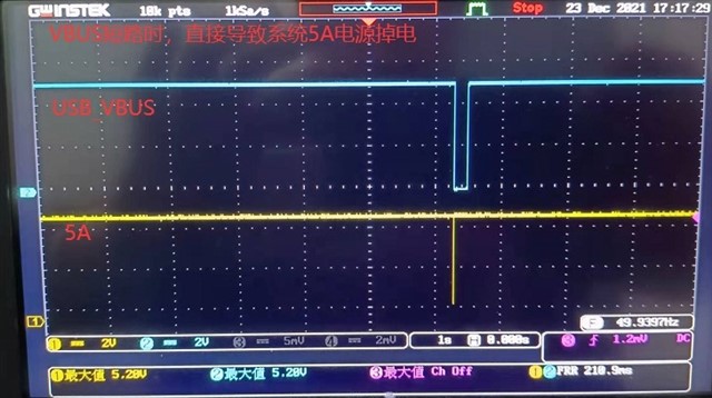
3) When the USB-A port is in short-circuited testing, the +V5P0A power supply of the system will be dropout, the waveform is as below:

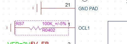
4) The power dropout problem is still exist when the OCL1 pin pull-down resistance set to 100KΩ,18KΩ,10KΩ or 6.2KΩ.

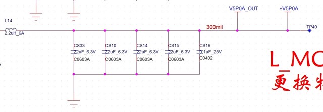
5) We have tried to added a 220uF capacitor in parallel above the +V5P0A power supply, whic can solve the problem. If the parallel capacitor is too small, there will still be a problem (for example, add three 22uF parallel capacitors).

Can u give us some suggestion for this problem? Added a big capacitor in paraller above the +V5P0A power supply is not suitable for the notebook project.

Thanks,

Best Regards

  • Hi,

    One question confirm with you, for output caps of V5P0A are all MLCC or not? if all are MLCCs, this may cause instability since 51285B is DCAP control mode, which need ESR compensation.

    Yuchang

  • Hi Yuchuang,

    I have confirmed with our customer and learned that the output caps of V5P0A are exist on the PCAB. Pls refer to the schematic as below:

    By the way, our customers have some questions about your reply, they want to make sure whether the output caps of V5P0A can be all MLCC capacitors? Is there any particularity in DCAP control mode? What kind of materials should be posted to this position?

    Thanks,

    Kind Regards

  • Hi, For Dcap control, there is LC double pole which need external ESR zero for compensation to make the loop stable. you can refer to page12 equation 2 for details of ESR requirement. generally MLCC has smaller ESR and can't meet it. Poscap or spcap or OS-can which has larger ESR can make it. and if customer must use MLCC, external Zero needed by adding external Ripple injection circuit. you can search the app note for details(SLVA453).

    Yuchang