Other Parts Discussed in Thread: , , TPS65982
Hello,
I am using the TPS55288QRPMRQ1 part on a board and I am unable to get it working with no progress or solutions. I have made sure that this is the I2C version. It has the same behavior on different boards with the same design. It is intended to be working as a boost convertor, taking in 5V and outputing 20V. Attached below is schematic for how we have the TPS55288 connected. One thing that was left out the design by mistake was a capacitor between Vout and Rsesne(R194) to ground, but this shouldn't affect the output when there is little to no load.
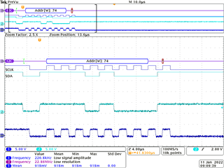
It will not communicate over I2C with a PIC microcontroller. This PIC is able to communicate with other TI chips on the board with I2C with no issues. It is not sharing I2C lines with any other chips so it should not be conflicting with anything else. Both the SDA and SCL lines are pulled up with a 1.5k ohm resistor to 3V3. On the oscilliscope, both lines are pulled up, and the correct address 0x74 is being sent. The address is set with a 0ohm on the mode pin.
The TPS55288 is also outputing the wrong voltage which was measured at 1.6V. This may be due to the fact that the 4h register is defaulted to 0 which uses the internal resistor divider but we would like to use the external one. We attempted to remove the external resistor devider R196 and R 200 and float the FB/INT pin. This resulted in the new output voltage reading 3V, but we are still unable to communicate with the device.
I have also tried increasing the ouput voltage from 5V to 20V and it had no impact on the output from the TPS55288. I am not sure what else to try at this point.
Please let me know if we are doing something wrong.