[Update Jan. 1 2022, well the low impedance on SW is due to the low impedance of the supercap of course. I will further investigate and update this post - please do not reply to this post for now!]
Hello there,
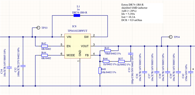
I am using the TPS61022 for a supercap-buffered power supply application.
One of our units works great, and the supercap discharges consistently from its design voltage of 2.36V down to about 0.5V. When I measure the resistance from SW to GND, it is very high (> 1 Mohm).
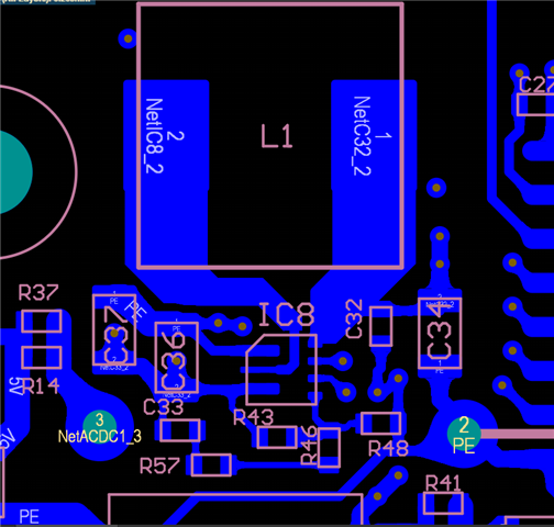
On 4 other units, I measure about 0.5 ohms from SW to GND. On two of these, tests showed that the supercap gets charged only to about 0.15V. I'm wondering if the TPS61022 have been damaged due to layout issues causing e.g. high SW node ringing (as discussed in other posts, such as
However, the other 2 have never been tested with an input voltage, and so should, if the laws of physics as we know them are on our side, not be damaged (but these also show low impedance from SW to GND!).
I am wondering which of the 3 cases is correct:
- the SW pin should or can be low impedance to GND by default, when measuring with a multimeter
- there is a solder problem shorting SW to GND under the chip
- the TPS61022 are damaged
Could you tell me if case 1 is true? I'll try to desolder one of the chips on a non-functional unit.
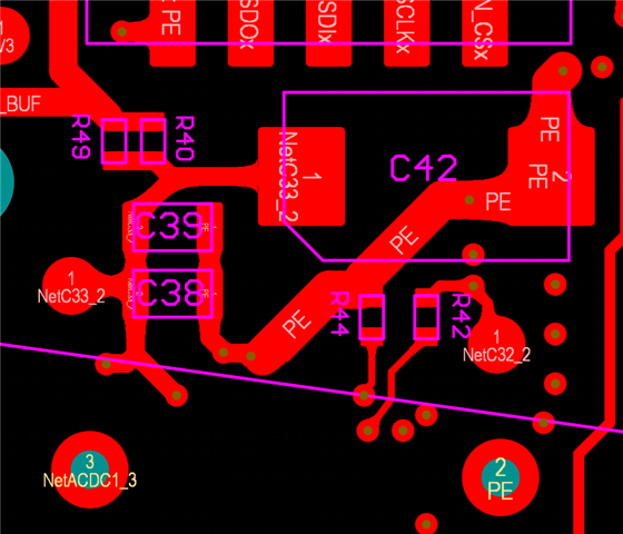
I'll attach a pic of the circuit. BTW: Vout connects to the 5V adapter input rail.
Thanks!