This thread has been locked.
If you have a related question, please click the "Ask a related question" button in the top right corner. The newly created question will be automatically linked to this question.
Hi,
Customer have confirmation regarding their design, please see details below.
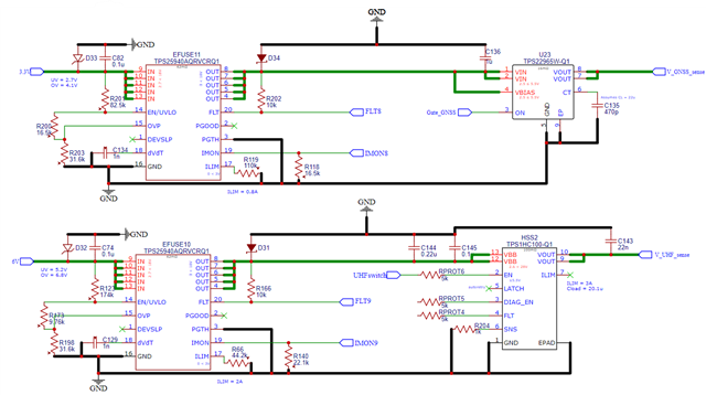
Based from "Basics of Power Switches" application report, I have designed these for my 2 subsystems: GNSS and UHF. Peak currents are (1.8W/3.3V) 0.54A and (10W/6V) 1.66A, respectively. Cload of UHF is confirmed to be such while Cload of GNSS is only assumed (I have no explicit value for Cload but they only told me that inrush current = 1.75A for 1.5ms only (https://docs.novatel.com/OEM7/Content/Technical_Specs_Receiver/OEM719_Electric_Environment_Specs.htm?tocpath=Specifications%7COEM719%20Technical%20Specifications%7C_____3)).
1. For UHF, since both efuse and high-side switch has current limit capability, I only employed this capability in the efuse and not in the HSS. I did this to reduce component count and save board space. Is this assured design? Is it better to implement current limit for HSS as well? I have no PCB layout yet for this. Please ignore HSS pins 2-6 for now.
2. For UHF, I defined the current limit to be 2A as a gut feeling only. I tried backing this up by computing for the Δt in the "inrush current" equation since I know Cload value. Δt = 20.1u (6 - 1.66*0.1)/ILIM = 117.263e-6 / ILIM. Ignoring specific application requirements such as system startup timing, how do I objectively know a good Δt (so I can know a good ILIM)?
3. For GNSS, the company informed me that inrush current = 1.75A for 1.5ms only. Since I plan to use a load switch, I understand that the inrush current is mitigated by adjusting the rise time using capacitor CT. In my design, I implemented a value of 470p for now. While the efuse implements a 0.8A current limit. I was wondering how can I solve for capacitor CT?
4. For GNSS, given what the company told me about the inrush current, is a load switch even the better option than HSS? I tentatively chose a load switch after thinking that the capacitive load isn't that high for GNSS (which I have no idea for now) and that the RDS_ON of the load switch is lower than any automotive-rated HSS.
Please let me know what you guys think.
"
Thank you in advance.
Regards,
May
Hi May,
Thanks for reaching out.
Please see my response:
1. For UHF, since both efuse and high-side switch has current limit capability, I only employed this capability in the efuse and not in the HSS. I did this to reduce component count and save board space. Is this assured design? Is it better to implement current limit for HSS as well? I have no PCB layout yet for this. Please ignore HSS pins 2-6 for now.
I am looping HSS apps engineer to help on this.
2. For UHF, I defined the current limit to be 2A as a gut feeling only. I tried backing this up by computing for the Δt in the "inrush current" equation since I know Cload value. Δt = 20.1u (6 - 1.66*0.1)/ILIM = 117.263e-6 / ILIM. Ignoring specific application requirements such as system startup timing, how do I objectively know a good Δt (so I can know a good ILIM)?
what do you mean by Δt? Can you explain the above equation? ILIM should be decided based on how much current downstream load can tolerate and it should be less than your power supply current limit. how much is cload in UHF path? after deciding ILIM you should decide inrush current which should be less than ILIM , once you decide inrush current then you can choose dvdt cap of efuse to decide charge time.
3. For GNSS, the company informed me that inrush current = 1.75A for 1.5ms only. Since I plan to use a load switch, I understand that the inrush current is mitigated by adjusting the rise time using capacitor CT. In my design, I implemented a value of 470p for now. While the efuse implements a 0.8A current limit. I was wondering how can I solve for capacitor CT?
Looping load switch apps engineer to help. I think 1.75A is the maximum value, you can keep inrush lower than that ?
4. For GNSS, given what the company told me about the inrush current, is a load switch even the better option than HSS? I tentatively chose a load switch after thinking that the capacitive load isn't that high for GNSS (which I have no idea for now) and that the RDS_ON of the load switch is lower than any automotive-rated HSS.
Regards
Kunal Goel
Hi May,
In reference to the High Side Switch and ignoring pins 2 through pins 6, the TPS1HC100-Q1 will default to its internal current limit of 3A. This is an acceptable use case.
Thanks,
Shreyas
Hello May,
Working backwards we can get an output capacitance value of 525uF from the inrush current equation using 1.5mS, 5V and 1.75A. Using this value you can calculate the inrush current for the given slew rate. For example:
CT = 470pF
SR = 962 uS/V
inrush current = Cload*dV/dt = 525uF *(1/962)(uS/V) = 546mA
You can then adjust the CT value based on your needs.
In terms of your question regarding whether high-side switch or load switch- they are both good for different reasons. A high-side switch has many more protection features, is able to sense and limit current, and it can handle inductive loads. Load switches are cost efficient, lower Iq and Isd, and control inrush current via SR control.
Regards,
Kalin Burnside
Hi Kunal,
Just received response from customer, please see details below.
"
1. Thanks! I wait for their response and hopefully they understand my questions.
2. Thanks for the tips. I have used the efuse calculator to decide on the values. Just to clarify: "Icharge-req" of the calculator is the inrush current in eq. 15 of the datasheet right?
On the side note, if I have a selected rise time for the efuse, how do I select the rise time for the load switch? Do I implement the same rise time to the load switch?
3. Yes, 1.75A is the maximum value. I think I will use the load switch calculator to control this inrush current for now. I will still wait for your teammates to reply tho
"
Regards,
Maynard
Hi Shreyas,
Please see response from customer regarding the implementation,
"
Thanks for the clarification but my concern is if I need to implement current limiting capability on both efuse + HSS or simply just efuse."
Thank you in advance.
Regards,
Maynard
Hi Maynard,
The HSS will default to its internal current limit of 3A. It is an acceptable use case.
Thanks,
Shreyas
Hi Maynard,
Please see response to these questions:
1. Thanks for the tips. I have used the efuse calculator to decide on the values. Just to clarify: "Icharge-req" of the calculator is the inrush current in eq. 15 of the datasheet right?
Yes that is the required inrush current.
The actual inrush current is set as per this field:
On the side note, if I have a selected rise time for the efuse, how do I select the rise time for the load switch? Do I implement the same rise time to the load switch?
You can keep same. eFuse would be slowing down VOUT rise thus slowing down VIN rise for load switch thus inrush current should already be less through load switch. You just have to ensure that overall startup time(efuse +load switch) is within your start time requirement and you have a successful startup. Charge time can be later adjusted during testing phase also by changing cap values.
Let me know if further concern or we can close the thread.
Regards
Kunal Goel