This thread has been locked.

If you have a related question, please click the "Ask a related question" button in the top right corner. The newly created question will be automatically linked to this question.

TPS54341: 24V to 5V Output Issues

Part Number: TPS54341
Other Parts Discussed in Thread: TPS54360

Hello,

I am using two TPS54341 components in my design, one for 24V-to-12V regulation and one for 24V-to-5V regulation. I have them configured for ratiometric startup and have simulated both using WEBENCH to get ballpark compensation components. Please see attached schematic snippet. Also please note there is another 100uF on the 5V rail at a different connector.

The 12V regulator looks fine, I've loaded its output with up to 2A and it seems stable. Startup conditions look good.

The 5V regulator however is producing higher output voltages with added load (steady state). At no significant load, it's at around 5.2V (which seems a little high but close enough  ). As I add resistive load to the 5V output (0.5A, 1A), its output voltage increases. With a 1A constant load, it rises to 5.8V. 
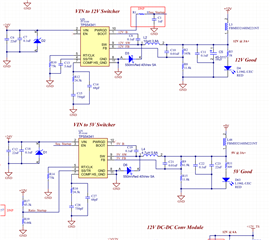
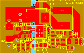
I have tried re-simulating, swapping out different values for compensation per the simulation (which says it should be stable), and also just in case, removed the ratiometric components and replaced with a Css of just 2.7nF. The 4.7uH inductor is rated for 5.8A, it's part number is: SRN8040TA-4R7M. 

I've run out of things to test and look at, the rising output voltage has me baffled. Any ideas? I did PCB layout per the datasheet and kept things clean. Please see attached screenshot of the 5V regulator PCB layout.

Thank you so much in advance for any feedback you can provide!

Jason Metzner

  • Hello Jason,

    Have you tried putting just a ceramic capacitor on SS pin for 5V rail to see if that results in normal device operation?

    SS pin control the FB voltage. I don't think your current implementation is acceptable for this device.

  • Hi Marshall, 

    Thanks for the response. Yes, I tried replacing the ratiometric components (removed both R17 and R19) and replaced with a 2.7nF cap to ground (where R19 was). No difference.

    Thanks!
    Jason

  • Hi Jason,

    Can you send some wave forms of the switch node with and without load?

    Thanks,

    Andrew

  • Hello Jason,

    I have attached the excel calculator for the product populated with your power conditions.

    It looks like the comp values may not be ideal. It might be best to change to the recommended values calculated.

    In addition, C21 is quite a large value feed-forward capacitor. If I had to guess, you maybe pushing your crossover frequency to a high value.

    Lastly, load capacitance is not often considered to be factored in to the required capacitance needed for stability especially when there could be an impedance between the buck inductor and load capacitance.

    I would recommended changing the comp values to recommended value, removing C21, and adding a few pieces of 22uF 16V caps next to the already populated 22u ceramic.

    The large feed-forward capacitor is applicable to both designs. Also, the 2nd stage filter is required to be damped to avoid impacting loop response.

    e2e.ti.com/.../TPS54360_2D00_361FAMILY_5F00_CALC_5F00_TOOL_5F00_REVE.xls:320:240]

  • Hi Andrew,

    Thanks for chiming in. Here are some screenshots.

    5V Switching No Load: taken on the 5V supply switching node, no load conditions.

    5V Switching 1A Load: taken on the 5V supply switching node, 5 Ohm resistive load.

    12V Switching No Load: taken on the 12V supply switching node, no load conditions (thought it might be useful for reference).

    Thanks,
    Jason

  • Hi Marshall,

    Awesome, thank you so much for your response. I don't see an attached calculator, would mind please re-sending?

    And sorry, would you mind please clarifying which 22uF cap you're referring to? There's C12 on the input and C23 on the output.

    I will try some of the hardware changes you've suggested and follow up with a response, probably tomorrow.

    Thanks!!
    Jason

  • Hi Jason,

    Here is the calculator:

    8358.TPS54360-361FAMILY_CALC_TOOL_REVE.xls

    Thanks,
    Andrew

  • Thanks Andrew, for some reason the other link wasn't working

  • Hi Everyone,

    Thank you again for the input and sharing the calculator, it helped greatly. Here's what I did on my end:

    -Removed C21

    -Removed R17/R19, replaced R19 with a 10nF cap

    -Replaced R16 with 17.8k resistor

    -Replaced C28 with 6800pF cap

    -Replaced C27 with 33pF cap

    -Added 47uF more capacitance on output (in parallel with C23)

    I will also be adding the UVHI and UVLO resistors in my next revision, but didn't think it was critical to this testing/investigation.

    The output now comes up as a pretty stable 5.01V, and with 1A, it changes to 4.99V and holds well. The switching node also looks a lot more like a square wave and seems to match the switching frequency.

    Thank you all!
    Jason