This thread has been locked.

If you have a related question, please click the "Ask a related question" button in the top right corner. The newly created question will be automatically linked to this question.

LM3488Q-Q1: LM3488: Issue when power on with load

Part Number: LM3488Q-Q1
Other Parts Discussed in Thread: LM3488, LM7480-Q1, LM3478

Hello,

I have a strange issue with LM3488 that happens only when my design has connected load. (> 0.5Amp) during startup.

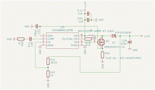
Input is 12V and configured output is 24V.

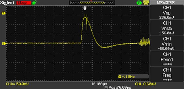
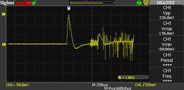
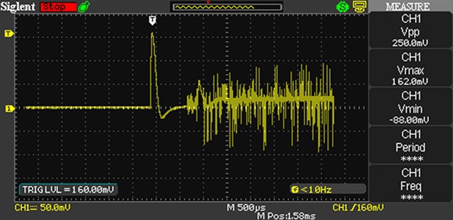
Seems that the LM3488 is locked at 50KHz (I measure 50KHz on FA/SYNC/SD pin) and N-Mosfet exhausts all available current of the power supply. (In my test case I have limited current to 5Amps)

If the circuit is connected  to power without load or load below 0.5Amp, it works as expected during startup. Measured frequency is 350KHz during normal operation.

Thank you for your help.

  • Hi Evangelos,

    it looks like you get over current detected due to the inrush current to charge the capacitor.

    Basically this should not get triggered at this time but maybe you are picking up some noise via the Rsense resistor.

    May can try to probe the voltage over this resistor and check if this is reaching the current limit.

    Best regards,

     Stefan

  • Hi Stefan,

    Indeed, I was thinking that a slow start ic like LM7480-Q1 Ideal Diode Controller with Load Dump Protection or an electronic fuse would help to deal with inrush current from capacitor but it increases the BOM cost.

    I have to fix the problem with the sense / overcurrent detection. I didn't include the 100Ohm resistor between Isense pin and Mosfet. Do you think that might be the issue here? 

  • Hi Evangelos,

    the R and C on the Rsense are for additional slope compensation. This might be required for your design to be added but should not have reason for the issue with the startup.

    As mentioned I recommend to measure the voltage on the RSense (please us the tip and barrel methode) and check if and when the current limit voltage level will be triggered.

    Ensure that the layout is proper for this path so that no error signal can be injected into that path.

    Best regards,

     Stefan

  • Thank you Stefan, I'll check the voltage on the Rsense and provide an update

  • I captured 3 jpgs from osciloscope during 12V insertion to the circuit.

    The short-circuit event happens only when there is load at the 24V output.

    Probe was place using tip /barrel method on the Isens pin of LM3488

    I can see a voltage spike / peak to 230-240mV and some noise but Vpp never exceeds 250mV.
    The short-circuit current limit gets activated when voltage is >350mV.  Do below images justify this behaviour?


  • Hi Evangelos, 

    Based on what you are seeing, it does appear that you are hitting the short-circuit protection since your switching frequency is reduced. I think what you may be seeing is additional effects from the internal slope compensation source, which may cause you to hit the threshold. In this case, I would recommend adding an external filter that has a time constant larger than the initial pulse width to dampen the spike at the CS pin. 

    Regards,

    Richard

  • Seems that the issue I encounter is fully covered here: https://e2e.ti.com/support/power-management-group/power-management/f/power-management-forum/180196/lm3488-possible-latch-up-mode

    It has to do with the slow start of my bench PSU, or current limit of 5A that the PSU apply.

    Last post:

    "The LM3488 is low side N-Channel MOSFET controller which is able to reach a 100% duty cycle. Unfortunately, the LM3478/88 gate driver could gets stuck generating a high driver signal that keeps the MOSFET turned on all the time when the IC hits 100% duty cycle if the input power supply is current limited.

    The problem occurs because the LM3488 doesn’t have an Under Voltage Lock Out circuit which turns off the device when the input voltage goes below a certain value. Without the UVLO the device will keep switching as long as the input voltage is higher than 2.97V (minimum input voltage). If the customer has set the maximum input current for an input voltage higher than 2.97V what happens is that the input current value will be higher than the maximum allowed at the start up causing the input current limit. When the input power supply goes in current limit, the output of the converter decreases then the duty cycle will increase because the device is trying to get more energy from the current limited input supply. Consequently, the low output voltage will cause the error amplifier to generate a high signal which doesn’t allow the intersection with the sense signal and then turning off the MOSFET. Furthermore the sense signal is no longer a ramp due to the current limit of the input power supply (the input power supply is current controlled instead of voltage controlled). This will cause the device to reach 100% duty which is basically a short circuit at the input."

    There is a solution with a diode / resistor on Vin pin able to bypass this situation I'll have to try that.

  • Hi Evangelos,

    thanks a lot for the info and update.

    Maybe you can let us know if this fix did help for you as well.

    Best regards,

     Stefan

  • Hi Evangelos,

    I assume this issue is solved and I am closing the thread.

    If there is still something open, just reply to open it again.

    Best regards,

     Stefan