Other Parts Discussed in Thread: BQSTUDIO
Hi,
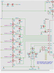
I was wondering if you could please confirm my circuit configuration for external balancing, specifically around the 6th cell?

I am experiencing an issue where Q3A is not turning on fully or at all, reducing balance current significantly on this cell.
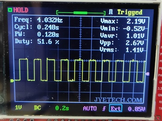
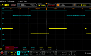
In this first oscilloscope capture for Cell 4, CH1 (Yellow) is the gate of Q4A, and CH1 (Blue) is the node between R21 and Q4A. You can see that Q4A is clearly turning on under control of the BQ40Z80, as evidenced by CH2 (Q4A Drain) being pulled low by around 4V, causing balance current to flow through the 51R resistor. (Note this was captured in Sleep mode, with CBS=1 hence the longer pulse times):
This is how I'd expect it to look for all cells undergoing balancing.
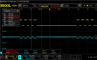
In the second capture for Cell 6, the same nodes are sampled around Q3A. Note that, despite the gate being toggled, the node at Q3A and R19 only drops by around 430mV, and thus a fraction of the desired balance current flows:
On a second battery pack I tested, the FET for Cell 6wasn't turning on at all.
These FET's have a very low VGHth of Max. 1.2V, so I would expect them to be fully on with 2V at the Gate. I suspect a biasing issue of some sort.
Note that the oscilloscope was grounded to Batt-. I plan to repeat the test with a battery powered scope grounded to the Source of each FET to confirm the Gate-Source voltage.
Any thoughts would be greatly appreciated!
regards,
Daniel