This thread has been locked.

If you have a related question, please click the "Ask a related question" button in the top right corner. The newly created question will be automatically linked to this question.

UCC21521: UCC21521 failure: OUTB shorted to VSSB and VDDB shorted to VSSB

Part Number: UCC21521


Hello,

My name is Abhishek K SIngh and I was using UCC21521 to provide gate signal to a Hex-bridge to control position of a BLDC motor. I have used three UCC21521 ICs, one to control one leg (high side MOSFET and Low side MOSFET) in the Hex-bridge. I'm using a bootstrap circuit along with UCC21521.

I was testing this motor with a spring load. There was some displacement command given to motor after which command was givcen so that it can come back to its natural position (when spring load is 0Nm).

While coming back to its natural position the MCB (16 A rated) put for protection of 150V motor battery power supply tripped. It was not know what has happened in the ECU so, MCB was swutched ON again but it tripped again, and there was a sound heard from the ECU. When we opened the ECU what we observed were as follows:

1) Capacitor C102 burnt and blown up along

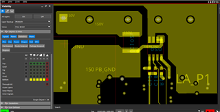
2) Current sensor U20 pin 3 & 4 to 150V PB_GND (150V power ground) track burnt and evaporated

3) MOSFETs Q2 and Q5 were showing short between Source - drain, source - gate and drain - gate.

4) MOSFET Gate drivers U1, U2 and U3 ( not shown in circuit but it controls third leg of Hex bridge) were damaged:

     a) OUTB - VSSB short was observed in all of them

     b) VDDB - VSSB short was observed in all of them

     c) OUTA - VSSA were not shorted

5) Output side of 28V to 15V DC-DC converter powering all the MOSFET gate drivers was shorted.

Schematics: UCC21521 ckt.pdf

I'm current in the process of root couse analysis for this failure and was to know what kind of electrical stress could cause the MOSFET gate drivers to fail in the way they have. Please help me regarding this.

I would also appreciate if you had any recommendation regarding the circuit,

Regards,
Abhsihek Kumar Singh

  • Hi Abhishek,

    Thanks for reaching out on E2E! We did not immediately see any major issues with the schematic you shared. However, please allow us a few more days to review it in more detail.

    In the meantime, I have a few follow-up questions to help us get a better understanding of the situation.

    • Can you share the layout as well?
    • Can you share more of the system conditions? (i.e. power level, switching frequency)
    • Have you tried to replace the failed devices and test the system again? Is the issue is reproducible?

    Thank you!

    Best,

    Olivia Brandel

  • Hi Olivia,

    Sorry for the delay.

    1. Power to UCC21521 was from 15V, 8W DC-DC converter.

        Motor power supply was 160Vdc

    2. PWM switching frequency was 20kHz, duty cycle varied from 0 to 100%

    3. Due to shortage of ICs we are still in process of procurement. When we get the new IC's we will test again.

    layout:

    Top layer: UCC21521 ICs (U1, U2 and U3)


    Bottom layer: Capacitor(C102) and current sensor (U20)

    Do you think that decapsulation of the ICs should be done to check what kind of failure has happened?

    Could you find any possible causes for failure after review which could explain the observations taken after failure?

    Regards,

    Abhishek Kumar Singh

  • Hi Abhishek,

    Thanks for providing the additional information!

    This type of failure is typically cause by overstressing the part (exposing the device to voltage outside of the abs. max. rating). In these cases, failure analysis is unlikely to provide any detail beyond this.

    Overall, many components are failing and it is not clear which is failing first. So, the main goal here would be to isolate the source of the overvoltage stress in the system. For reference on avoiding overstress, the device datasheet lays out some design best practices in sections 9 through 11. Once you are able to obtain new ICs, here are some other things that would be helpful to investigate:

    • Measuring the bridge control signals from the microcontroller (and the resulting driver outputs)
      • Since all three drivers are being short-circuited, it’s possible that the control method could be part of the problem.
    • Measuring other critical waveforms of the system (VDD, FET VDS, current, etc.)

    Additionally, I have a few more follow-up questions:

    • How long did it take to see the failure?
    • What are the part numbers of the FETs?
    • Can you share a layout image showing the traces that connect the gate drivers to the FETs?
    • Can you share a layout image showing both the top and bottom layers? We would like to see where the bottom layer traces are with respect to the top layer.

    Thank you!

    Best,

    Olivia Brandel