This thread has been locked.

If you have a related question, please click the "Ask a related question" button in the top right corner. The newly created question will be automatically linked to this question.

BQ76952: Why can't BQ76952 enter shutdown mode?

Part Number: BQ76952
Other Parts Discussed in Thread: BQSTUDIO, EV2400

Hello everyone

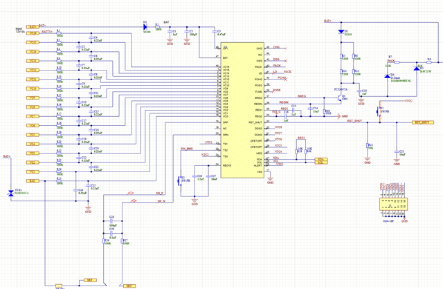
‎I only use BQ76952 to monitor the battery voltage, current and temperature, using the default configuration, when I give the RST _ SHUT pin a high level, the pin measuring TS2 does not output a high level?

According to DATASHEET, TS2 should output a high level in shutdown mode.

There is only one normally open switch connected to the TS2 pin.

THANKS!

Xia Chime

  • Hello Chime,

    What is Vcc? I would recommend you measure the REG18 pin to check if the part is in SHUTDOWN. If the part is not in SHUTDOWN, you will measure ~1.8-V here.

    The TS2 pin is very weakly pulled high during SHUTDOWN, so it is easy for it to be pulled low and could be pulled to a lower voltage when measuring with a probe or multimeter.

    Best Regards,

    Luis Hernandez Salomon

  • Hello Luis H.S.

    Thank you very much for your prompt reply!

    My VCC is 5V, and when I supply a high level to RST_SHUT for more than 1 second, the measured REG18 is still 1.8V. I did measure it with a multimeter.

    Will REG18 have no voltage output in shutdown mode? So this means that my device did not enter the shutdown mode, what is the reason?

    Best Regards,

    Xia chime

  • Hello Chime,

    Something that I noticed, is that the LD pin is connected to PACK. Since the DSG/CHG FETs are not being used, you should connect LD to Vss.

    If the LD pin is above the VWAKEONLD voltage, the part will never be able to enter SHUTDOWN, it would only be able to enter a state called "soft shutdown". This is described in the last paragraph of Section 7.5 SHUTDOWN Mode in the TRM. I believe your part is entering "soft shutdown".

    Best Regards,

    Luis Hernandez Salomon

  • Hello Luis H.S.

    Thank you very much for your prompt reply!

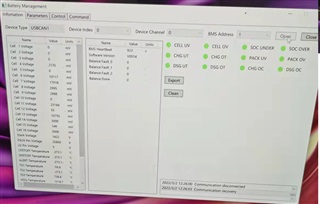
    I connect the LD to GND and give the RST _ SHUT shutdown signal to put the device into shutdown mode. And TS2 is measured to have a high level output, REG18 is also measured to have a voltage of 0. But my upper computer reads that the voltage of LD is not 0, but changing. Why is that?

    Also, if I give TS2 a low level but do not wake up the device. My host computer can't measure the cell voltage. As shown:

    When I give TS2 a low, REG18 has a voltage (1.79V).

    Best Regards,

    Xia chime

  • Hello Chime,

    If TS2 is high and REG18 measures no voltage, the device is in SHUTDOWN, it is not able to communicate at all. So whatever you are reading from LD is not coming from our IC.

    Your device sounds like it is ON after pulling TS2 low. If you reset the program or IC, does the cell readings go back to normal? Are you using all 16 cells?

    After SHUTDOWN the part resets to its default settings, did you do any OTP programming? Or is it being programmed on the spot?

    Best Regards,

    Luis Hernandez Salomon

  • Hello Luis H.S.

    Thank you very much for your prompt reply!

    After pulling TS2 low, REG18 measures that there is voltage, but the battery reading is still chaotic. I reset the software and can't read the battery voltage properly. Only by switching the power supply again can the battery voltage be read normally.

    Currently in the debug phase, the OTP is not programmed, and the OTP is kept at the default setting. 

    Best Regards,

    Xia chime

  • Hello Chime,

    What are the gate-source voltages of DSG/CHG at this point?

    What part number do you have?

    If you use the EV2400 from the EVM to communicate with the part using bqStudio, do you still see this behavior?

    Best Regards,

    Luis Hernandez Salomon

  • Hello Luis H.S.

    Thank you very much for your prompt reply!

    I did not use the DSG and CHG functions, so it is floating.

    I use BQ76952PFBR.

    The values I read out with the EV2400 communication seem to be stable, due to the EV2400 EVM being corrupted during debugging. No more tests now.

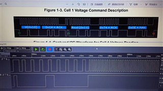
    My own PC communication is always unstable, BQ76952 often no response, need to restart the power supply can be. The waveforms I measured are as follows:

    Best Regards,

    Xia chime

  • Hello Chime,

    Your part number does not have REG1 enabled by default, are you pulling up your communication pull-up resistors with an external power supply? There are pull-up resistors on the EV2400 side, so REG1 is usually not needed when using the EV2400. However without it, REG1 needs to be enabled or an external supply is needed.

    If the EV2400 is working then it is likely that there is an issue with the pull-ups as I mentioned above, or with your code. Have you compared with our example code and training videos?

    Best Regards,

    Luis Hernandez Salomon

  • Hello Luis H.S.

    Thank you very much for your prompt reply!

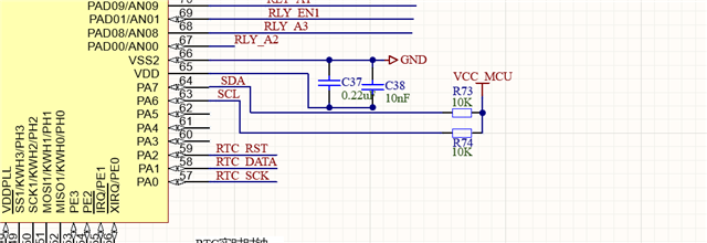
    I have a pull-up resistor at the MCU termination. The pull-up resistor at the BQ76952 terminal is optional, and I used the pull-up resistor at the MCU terminal during debugging. The circuit is as follows:

    I am using MC9S12XET to communicate with BQ76952. Now the problem is that a few minutes of work can not communicate with the BQ76952, to restart the power supply to do.

    I suspect that the problem is the code, I wonder if the EV2400 code can be ported to the MC9S12XET? Do you have any good suggestions?

    Best Regards,

    Xia chime

  • Hello Chime,

    The EV2400 code is confidential and we cannot provide it. We have example microcontroller code using I2C, which you may take a look in order to develop/correct your own:

    https://e2e.ti.com/support/power-management-group/power-management/f/power-management-forum/1082085/faq-bq76952-are-microcontroller-code-examples-available-for-the-bq769x2-battery-monitors

    Best Regards,

    Luis Hernandez Salomon

  • Hello Luis H.S.

    Thank you very much for your prompt reply!

    I also ask if my BQ76952 supports CRC? As shown in the figure below, what does N mean in the data?

    If so, do I have to make any changes to the hardware?

    Best Regards,

    Xia chime

  • Hello Chime,

    N means No. So CRC is not enabled in your device. If CRC is enabled, all the changes would have to be done in the software.

    Best Regards,

    Luis Hernandez Salomon

  • Hello Luis H.S.

    Thank you very much for your prompt reply!

    Now that the CRC problem is solved, the battery voltage reading is basically stable. After shutdown, pulling down TS2 is still unable to read the new value, but the measured REG18 voltage rises to the normal 1.8V. The BQ76952 must be powered off before it can be read. Please also guide.

    Thanks

    Best Regards,

    Xia chime

  • Hello Chime,

    The device should be able to communicate. How are you shutting down the device?

    Do you program any settings with the MCU after wake-up? 

    Do you see any issues in the I2C signal when this happens? Do you have an additional EVM or EV2400 to try testing with these and see if it works?

    Best Regards,

    Luis Hernandez Salomon

  • Hello Luis H.S.

    Thank you very much for your prompt reply!

    I use a key to TS2 through the 50k resistor to the ground to wake up.

    The MCU did not make any changes after waking up and did not receive an answer from BQ76952.

    I have seen that EV2400 has PACK pin connected to MosFet, but I connect PACK pin directly to Bat, is BQ76952 unable to wake up because of this?

    I don't have theMSP430F5529IPN, and I haven't repaired the EV2400, so I can't verify it with EV2400 for the time being.

    Best Regards,

    Xia chime

  • Hello Chime,

    Can you clarify your EV2400 connection? You should not be connecting it to PACK+ or BAT at all. The EV2400 only really needs to connect to the SDA/SCL communication signals and connect the Vss of the EV2400 to the PACK- reference.

    Do you have an EVM with an EV2400 on-board that you can test with? After WAKE-UP it should be able to communicate with your MCU. If you reset the device (through the RST pin) after WAKE-UP is there any change? If you reset your MCU alone while keeping the BQ76952  ON, is the issue resolved?

    Best Regards,

    Luis Hernandez Salomon

  • Hello Luis H.S.

    Thank you very much for your prompt reply!

    I used EV2400 debugging, it can wake up.

    I would like to ask, if I do not use the pack and LD pin function, is the pack and LD pin connected to high or low level?

    Best Regards,

    Xia chime

  • Hello Chime,

    You need to use the LD pin if you are using the DSG FET, this must be connected to PACK+. If not using the DSG FET, the LD pin can be connected to PACK+ or Vss. As recommended in Section 16.6 Unused Pins in the datasheet.

    The PACK pin could be connected to PACK+ or Vss. 

    This was answered in a previous E2E thread: https://e2e.ti.com/support/power-management-group/power-management/f/power-management-forum/966107/bq76952-pack-and-ld-pin-functionality-questio

    Best Regards,

    Luis Hernandez Salomon

  • Hello Luis H.S.

    Thank you very much for your prompt reply!

    Yes, before debugging, I connected the LD and pack pins to pack + according to this suggestion. When debugging this time, I found that I could not enter the shutdown mode through RST _ SHUT. You suggested that I connect the LD to VSS. If you want to shut down through RST_ SHUT and wake up through TS2, do LD and PACK need to be connected to VSS under such conditions?

    Best Regards,

    Xia chime

  • Hello Chime,

    If there is a voltage on the LD pin the part won't be able to SHUTDOWN fully. So yes, you need to connect LD to Vss if you want to shutdown with RST_SHUT and wake through TS2. Since you are not using DSG/CHG FETs there will always be a voltage on the LD pin if connected to PACK+. The only pins that affect SHUTDOWN are LD and TS2. The PACK pin could still be connected to either PACK+ or Vss.

    Best Regards,

    Luis Hernandez Salomon

  • Hello Luis H.S.

    Thank you very much for your prompt reply!

    I've solved it! When I debug, the MCU is always powered on, but when I actually shut down, the MCU is not powered on. I reset the MCU after power off OK.

    Best Regards,

    Xia chime