A related question is a question created from another question. When the related question is created, it will be automatically linked to the original question.
If you have a related question, please click the "Ask a related question" button in the top right corner. The newly created question will be automatically linked to this question.
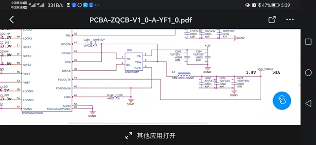
I use TPS6508641 PMIC ,but SW6 output is 6V~8.5V , I need 1.8V , whether need divider resistance?if yes, how to select resistance;my schematic is as below ,please help me check;
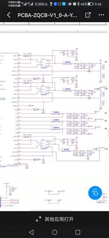
Thanks for posting this question on E2E. Could you please provide a PDF version of the schematic where we can clearly see all the connections for the PMIC and the external components? Could you also provide a scope capture of the power-up sequence showing Buck5, Buck2, Buck1 and Buck6?
Where the equations on the datasheet (section 9.2.1 Design Requirements) used to calculate the inductor as well as the output capacitance and ILIM resistor for each of the Buck controllers (Buck1/2/6)?
Thanks for providing the schematic and scope captures! Here are my questions and feedback:
Where the equations on the datasheet (section 9.2.1 Design Requirements) used to calculate the inductor as well as the output capacitance and ILIM resistor for each of the Buck controllers (Buck1/2/6)?
What is the max load current you are expecting on Buck6?
Why is Buck2 using a resistor divider? Only Buck1 supports the "EXT FB" when used to generate 5V.
Is signal "PL_PWR_EN" controlled by the processor/SoC? On this device (TPS6508641 specifically), the load switch SW_B12 (pin#17 / #19) and LDOA3 are enabled with CTL5 which seems to be pulled up to the 3.3V internal LDO. The problem here is that load switch as well as the LDOA3 could be enabled before the supply (Buck6) is available. This could cause a power fault.
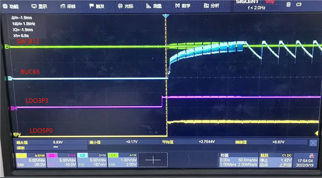
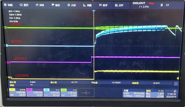
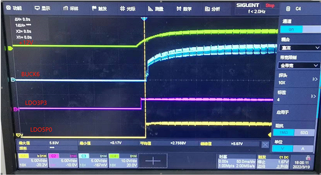
Could you provide a power up capture showing LDO5P0, LDO3P3, Buck6, SW_B12 (VCCAUX in your schematic), LDOA3 and "+12V"?
1. schematic refer to XCZU5EG , inductance calculation is within range;
2. The partial pressure is 100 to 10K, which is basically the same as the differential pressure. Test the same effect without the partial pressure connection
3."PL_PWR_EN" is designed to start up automatically without any other main control
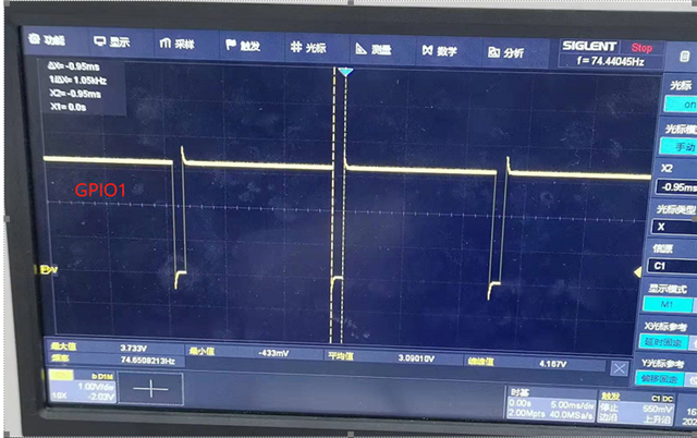
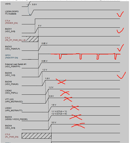
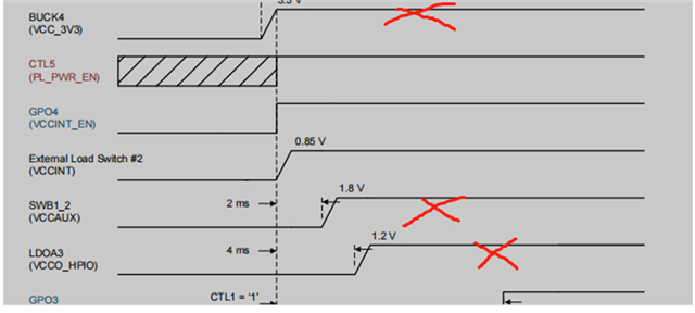
4.At present, it is found that the output voltage of Buck6 is high (Buck2 0.85V normal, Buck5 1.2V normal), SW_B12, LDOA3, Buck3, Buck4 also have no output voltage now, I don't know where the debugging caused. GPIO1 outputs a special frequency pulse signal
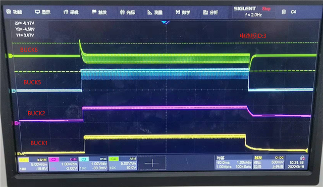
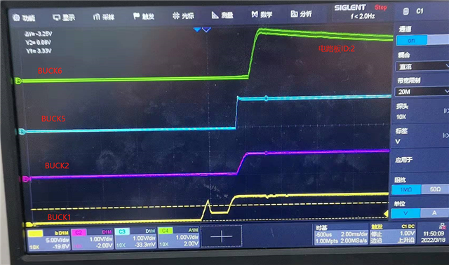
The current power supply status, after buck6 start up, the power is abnormal as below, marked “X” output power is almost zero, very low, does this power supply have sequential characteristics?
Thanks for sharing the waveforms! Here is my feedback:
Buck6 seems to be enabled when the "+12V" supply is very close to the min input voltage on the spec. The minimum input voltage for the Buck controllers (Buck1/2/6) is 5.6V and as you can see from the scope captures, Buck6 starts ramping up when the input voltage is equal to (or below) the min threshold.
How was the resistor on the ILIM pins calculated? Could you share the details? ILIM6 has a 2.37K Ohms and it seems too small.
What is the max current you are expecting on each of the buck controllers?
Why is Buck2 using a resistor divider? Only Buck1 supports the "EXT FB" when used to generate 5V.
Are you able to measure the current on each of the Buck controllers?
Could you measure the current going out of the +12V supply?
What are the current capabilities of the regulator supplying the +12V?
Here is what I recommend for the next steps:
remove the load from all the PMIC rails (if possible) and re-take the power-up captures.
increase the resistor on ILIM6.
Hold CTL4, CLT3, CTL5 and CTL1 low until the "+12V" supply is stable at 12V. This can be done by soldering a wire on the side of the pull-up resistor that is connected to the CTLx pin.