This thread has been locked.

If you have a related question, please click the "Ask a related question" button in the top right corner. The newly created question will be automatically linked to this question.

LM5060-Q1: Not working properly

Part Number: LM5060-Q1

Hello Sir,

I am using LM5060MM/NOPB for the load Switch application.
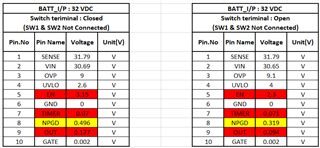
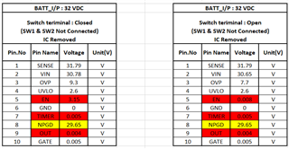
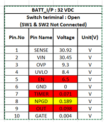
Input Voltage: 32VDC
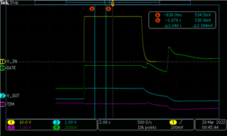
Output Voltage: 0.098 after Enable the LM5060MM/NOPB

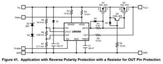
TI Test.pdfPlease find the attached schematic and Voltage readings across every pin.

Please review the schematics and suggest the changes.

Regards
Murthy

  • Hi Murthy,

    Can you share the startup test waveform (Vin, vout, Timer voltage, input current, GATE)

    Best Regards,

    Rakesh

  • I replaced IC and Mosfet Still not working, My gate signal always staying low, nPGD pin is getting Low and Led is ON.

    Captured the image

    Please find the attached image.

    Please give your suggestions as soon as possible

    Regards

    Murthy

  • Hi Murthy,

    As per the resistor divider network on OVP pin, it voltage should be around 0.95V for Vin = 32V.  Why is the OVP pin voltage at 9.3V in your circuit ? The Gate will be pulled low when OVP pin voltage is  > 2V. Can you check the resistance values of R99, R81, R80, R82.

    Similarly, check the connections of UVLO pin as well. 

    Also, Have you designed the circuit to protect from input reverse polarity condition like shown below?

  • Hello Sir,


    I replaced IC and Mosfet Still not working,
    Please find the readings

    Sir, We don't require reverse polarity protection in our System,
    I have checked the R99, R81, R80, R82 Values, It is mounted the same as the schematic attached.

    I am just wondering, why it is not working, Please let me know if any other reasons are there?

    I have purchased ICs directly from Texas Instruments, but it is not working.

    Regards
    Murthy

  • Hi Murthy,

    UVLO and OVP are high impedance pins. They draw almost 0A of current.  So, if the resistor divider network is correct the voltage should be OVP pin should be = 0.95V for Vin = 32V. 

    Please remove the IC from the board and check the resistor divider network voltages at each node. This will help us understand if the issue is with the IC or with the board.

  • Hello Sir,

    Please find the attached readings after IC was removed from the PCB.

    You are right, there is a problem with the PCB.

    Resistor values are correct, But why it is showing 9.3V at OVP Pin. I am confused.

    What might be the reason?

    Regards
    Murthy

  • Hi Murthy,

    I am not sure what is the problem in the PCB. I can suggest you start debugging the issue with PCB by checking the trace connections and voltages at different nodes between BATT_I/P, UVLO, OV and GND.