This thread has been locked.

If you have a related question, please click the "Ask a related question" button in the top right corner. The newly created question will be automatically linked to this question.

BQ76940: Testing development board for Battery Management System

Part Number: BQ76940

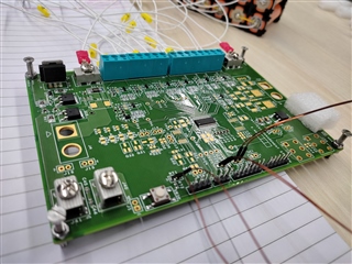
I have prepared a BMS development board for 15 cells using BQ76940 in low side configuration. I have not interfaced a microcontroller yet and presently testing out the hardware part.

When I check the voltage across PACK+ and PACK- (output terminals), it reads 50V. As soon as I connect a load across the terminals the voltage reads 0V. Is it normal? Is there anything I can do to prevent this?

Regards,

Cleatus Wesley

  • Hi Cleatus,

    I think the first thing to determine is the state of your protection FETs when this happens. Measure the gate of each FET to see what the BQ76940 is driving on the CHG and DSG pins. In the datasheet for the BQ76940, Table 8-1 shows which FETs are disabled for each type of protection. This will help narrow down which of the protections may be triggering. Then you can check the conditions on the hardware to determine the cause of the protection triggering.

    If you are able to connect to the I2C to read the status registers from the device, it will make debug easier. Without a microcontroller configuring your protection thresholds, it may be that you are running into an issue with the default settings.

    Hope this helps.

    Best regards,

    Matt

  • Could it be because of leakage current? When I connect a small load across the output terminals, the voltage goes to 0V immediately.

  • Hi Cleatus,

    That may be possible, but seems unusual. Did you check the state of the FETs?

    Matt

  • The gate of discharge MOSFET read 16V.

    Can the following algorithms be implemented in this IC?:

    JEITA Algorithm

    Enhanced charging

    Adaptive charging

  • Hi Cleatus,

    I need more information to help you debug this issue. Can you please respond to each question below?

    When you say the voltage reads 0V, what does this mean? Are you measuring the voltage at PACK+/PACK- with a multimeter? Is this the voltage reported by the BQ76940 IC when you read from the voltage measurement registers? Please give more details.

    When this issue happens, what is the voltage on the CHG pin and the DSG pin of the BQ76940? 

    Can you read the status registers of the BQ76940 when this happens to see if there are any protections triggered or faults reported?

    The BQ76940 is a battery monitor and does not control the charger (it does not support the algorithms you mention). There is a BQ78350-R2 companion controller that supports JEITA and this device also does gauging.

    Best regards,

    Matt

  • When you say the voltage reads 0V, what does this mean? Are you measuring the voltage at PACK+/PACK- with a multimeter? Is this the voltage reported by the BQ76940 IC when you read from the voltage measurement registers? Please give more details.

    I have not interfaced a microcontroller yet. I just powered ON the IC and checked the voltage across PACK+/PACK- to be 48V. Shouldn't it be 0V? The gate voltage to the MOSFETs read 0V,

  • Hi Cleatus,

    When the FETs are disabled, PACK- will be floating, so the voltage when there is no load does not mean much. When you apply a load, this will go to zero since the circuit is open. To enable the FETs, you need to boot the BQ76940 IC (rising edge on TS1 pin) and the microcontroller needs to enable the FETs. Then you will see the battery voltage on PACK+/PACK- when the load is applied.

    Regards,

    Matt