Because of the holidays, TI E2E™ design support forum responses will be delayed from Dec. 25 through Jan. 2. Thank you for your patience.

This thread has been locked.

If you have a related question, please click the "Ask a related question" button in the top right corner. The newly created question will be automatically linked to this question.

UCC28C43: UCC28C43 flyback transformer 160V-12V simulation convergence error

Part Number: UCC28C43
Other Parts Discussed in Thread: TINA-TI

Hi guys,

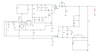
I am trying to design a flyback converter with the UCC28C43 controller and used the webench to get a circuit. Now I am simulating the design in TINA-TI.

However I am getting convergence errors with the values suggested by the webench. Does somebody have an idea what i am doing wrong?

I've read in an other post that changing some analysis parameters may solve this problem, but I am not sure which ones I need to change.

Or is my problem in the circuit design itself? I couldn't find the optocoupler model that the webench suggested (4N45VM) and just used another one I found. So maybe my feedback isn't stable anymore? I tried to design the flyback so that it would operate in CCM.

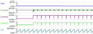
another thing I noticed is that just before the error occurs the voltage at the source of the MOSFET becomes to high for the MOSFET, I don't however know if this is the reason for the errors or just a consequence of an earlier fault.

 flybacksim.TSC

  • Anton,

    I changed your MOSFET model since the one you were using was giving the convergence error. The sim now runs without convergence errors but still need lots of work. Look at the TINA sims given in the GP PWM product folders and find an appropriate transformer model you can modify. Your existing transformer modal doesn't seem to have any mag inductance specified? Use TI Power Stage Designer to define your power stage parameters and also there is a loop calculator tool within Power Stage Designer. You can use the loop calculator tool to simulate the control loop parameters. 

    Regards,

    Steve M

    flybacksim_TI Edit_05032022.TSC

  • Hi Steve,

    Thanks for your reply. The MOSFET did indeed cause the convergence error. However the one you replaced it with doesn't seem to conduct at all, since the voltage at it's source pin stays high and the only thing I measure at CS is the slope compensation signal.

    I now replaced the MOSFET with a model already include in the TINA libs (IRF840), but the output still remains at zero.

    This is probably the fault of the transformer, like you suggested. Can you elaborate on where I can find the "TINA sims given in the GP PWM product folders", I'm sorry if this might be an obvious question, I'm not used to working with TINA yet and i can't seem to locate what you meant. 

    The Power Stage Designer is a tool I didn't know about yet, and I will definitely look into this further to optimize my Power Stage and Control Loop, but I assume the biggest problem now lies with my transformer model.

    Regards Anton

  • Anton,

    Attached is another TINA sim transformer example. Also, please refer to this E2E post for help on building a transformer model in TINA. Beyond these two examples, since TINA is a DesignSoft/TINA program, support questions are handled by using the DesignSoft support page: http://www.tina.com/technical-support/  .

    The DesignSoft/TINA team is very helpful and this is the most direct way for TINA support.

    Regards,

    Steve M

    slvm045_Tran Model_TINA.tsc