This thread has been locked.

If you have a related question, please click the "Ask a related question" button in the top right corner. The newly created question will be automatically linked to this question.

TPS650861: Programming guide request

Part Number: TPS650861
Other Parts Discussed in Thread: USB2ANY, , MSP430F5529, IPG-UI

Hi Expert,

what's your recommendation for TPS650861 programming as below:

offline programming, online programming  or programming from EEPROM?

1. offline programming: which means program the script file to single device then mount to MB. 

2. online programming: which means to mount the device on the MB first, then program it from BMC.

3. EEPROM programming: which means to mount the device on the MB first, then only provide standby power, host to program device from EEPROM.

Another questions for USB2ANY, Customer need it to communicate with device, but the USB2ANY out of stock now, who is right contact window for apply? 

Regards,

Mark

  • Hi Mark,

    I would probably recommend the offline programming since we have a few tools that can help with this process. We currently have a BoosterPack for the TPS650861 device that I will link below. The package comes with a blank chip to program and you can also get a Launch Pad device that makes the programming process much easier.

    If you have both of these devices you can use our OTP Generator to create the programming script. You can also use our IPG-UI software to interface with the BoosterPack / LaunchPad and do the programming you need on the chip. More information can be found in the user guide for the above devices. If you do programming once the chip is already on the MB, you will need a way to apply 7V to the CTL4 and the IRQB pins for the programming process. This is already done for you with the BoosterPack. I will also link the OTP Programming Guide below.

    BOOSTXL-TPS650861

    MSP430F5529 USB LaunchPad development kit

    TPS65086100 Non-Volatile Memory Programming Guide

    As for the USB2ANY availability, if you cannot find a unit from a reliable third party distributor, then no more unit will be available until we restock our inventory. In the mean time you can always go to the USB2ANY product page and click the "Notify me when available" option so you don't miss the next batch. There's also a link to buy from a distributor if you have not checked those options yet.

    Regards,

    James

  • Hi James,

    Thanks for your comments. 

    Regards,

    Mark

  • Hi James,

    as you mentioned "If you do programming once the chip is already on the MB, you will need a way to apply 7V to the CTL4 and the IRQB pins for the programming process", do you mean we need to apply 7V on CTL4 and IRQB always as the device mounted on MB? 

    Regards,

    Mark

  • Hi Mark,

    No, these pins can be pulled up to their normal 1.8V or 3.3V source through a pull-up resistor if not being used for programming or for burning in the OTP.

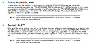
    To be clear, CTL4 only needs 7V when you want to enter programming mode and change register values in the 0x38 I2C address. This is where you can find the default power up settings registers and the OTP programming register (R = 0x02). Registers in I2C address 0x5E should not need this voltage (things like changing the power rail output voltage).

     If you want to burn in your OTP settings, you must apply 7V on CTL4 to be in programming mode and get access to the 0x38 address. Then you apply 7V on IRQB and change the PROGRAM_OTP bit to "1" in register 0x02 to start the burn process. IRQB voltage should not go below 6.7V during the burn process. Once the burn is complete and you are done programming, you can reduce the voltage on these pins again.

    Pin descriptions from datasheet:

    OTP Programming Application Note excerpt:

    Regards,

    James

  • Hi James,

    Customer use IPGUI to program IC on BOOSTXL-TPS650861 EVM, but without MSP430F5529 LaunchPad, so they are add 7V of external power source on CTL4 & IRQB. then remove 7V after programed, but BUCK1/2/3 are no output, do you have step by step document guide me how to confirm the programming procedure without MSP430 MSP430F5529 LaunchPad? 

    Regards,

    Mark

  • Hi Mark,

    Usually the IPG-UI software looks for a connection to the device through the MSP430F5529LP. If you are not using the launch pad, can you describe to me how you are connecting the device to IPG-UI so that I have a better understanding? 

    Check out this other thread I made where I discuss the programming process in more detail.

    https://e2e.ti.com/support/power-management-group/power-management/f/power-management-forum/1104150/tps65086100rskt-burn-the-second-otp

    After you are finished programming, you should power cycle the device to check whether your settings in the OTP registers are reloaded correctly. If the registers do not match your custom settings after a power cycle then there was an issue with the programming process. If the device has correct register settings but the buck regulators have no output / irregular output then there is likely a power fault.

    Regards,

    James

  • Hi James,

    Customer use USB2ANY to communicate with EVM board. they can program LDOA1, and have voltage output on LDOA1, but still no output at BUCK1~6. and LDOA2~A3.

    please see as below attached from customer programming setup.

    hope your comments is helpful to us to clarify it.

    TPS650861 programming issue 20220607.pptx

    Regards,

    Mark

  • Hi Mark,

    Thank you for sharing the set-up. I will take a look and provide an update within 2 business days.

    Regards,

    James

  • Hi James,

    the issue was fixed, it's working now.

  • Hi Mark,

    I'm glad to hear that it's working. Let us know if you have any other questions about the device here on E2E!

    Regards,

    James

  • Hi James,

    Another question for Script Generator sheet of TPS65086100 OTP Generator Excel file. 

    does it only fill in register value with manual? can we use IPGUI to export the Script Generator sheet? or any automatic  of method to export it?

    and do you have example file could to share with me ?

    Regards,

    Mark

  • Hi Mark,

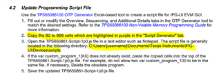
    Once you get to the Script Generator, you can follow the instructions in the picture below. This comes from the BOOSTXL-TPS650861 EVM User’s GuideAfter you complete these steps you can move to the next section of the set-up process.

    I usually open the TPS650861-Script-xxx.js  file with Notepad to paste in the script. 

    You may notice that there is already a script inside the file. This script can be either left alone or deleted. If you leave the original script in the file, just make sure that the new script you paste inside has a different name at the top as pictured below:

    These are two different custom scripts pasted into the file. As long as you change the highlighted hex numbers to a unique code for each script in the file, you should have no conflicts. The order of the scripts does not matter (the FF script can be pasted before the 00 script with no issues for example).

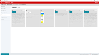
    Once you do this, you should be able to see each individual custom script in the IPG-UI device screen shown below:

    You can see the two highlighted custom scripts are displayed in the drop down list (plus some others that were not shown).

    Regards,

    James