Other Parts Discussed in Thread: TPS2663, LM5176
Hi team,
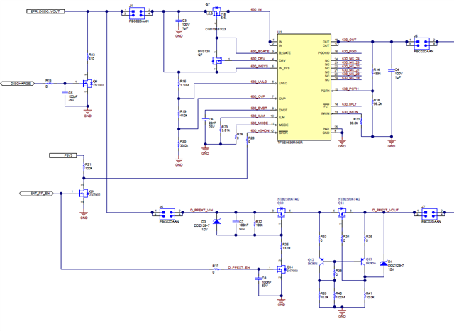
customer want to know what's the mechanism of OVP and OCP in below design, how can it handle dynamic Vout in PD3.1 (28,36,48V) ?
would you elaborate it for me, thanks

This thread has been locked.
If you have a related question, please click the "Ask a related question" button in the top right corner. The newly created question will be automatically linked to this question.
Hi team,
customer want to know what's the mechanism of OVP and OCP in below design, how can it handle dynamic Vout in PD3.1 (28,36,48V) ?
would you elaborate it for me, thanks

Hi Fred,
Thanks for reaching out!
For TPS2663, the reverse current blocking feature and OVP helps to handle dynamic Vout situation. On the second channel, D4 controls the Q11 for clamping the transients voltages at the Vout but I need to look into specific on how it functions for OCP. I will check and get back by Monday.
By the way, from where did you get the schematic ?
Best Regards,
Rakesh
Hi Rakesh,
I thought the second channel is the other method without IC, so are they working together?
yah, might need you elaborate on OCP control to dynamic vout. thanks
Hi Fred,
The second one provides a parallel path. Can you check with the customer on the purpose of adding it ?
Best regards,
Rakesh
Hi Rakash,
let's take this one by one , starting with OVP, and then OCP
how should I adapt dynamic Vin under PD3.1 , the Vin may be 28, 26,48V ?
use external logic circuit to control and connect different parallel resistor with R3 correspondingly?
Hi Fred,
I think so, I don't have idea on how they implement at system level.
The current limit for TPS2663 can be adjusted dynamically by switching the current limit resistors at ILIM pin as shown below

Best regards,
Rakesh
Hi Rakash,
I believe this document is straight from TI internal,
so I'm quite shock that you haven't seen this before. would you check internally if someone know this design?
and how about the OVP, can they use the similar method to implement dynamic OVP?
Hi Fred,
I have not seen this document before. I will check internally.
Best regards,
Rakes
Hi Fred,
None of our team mates are aware of this document. In the schematic, I see the feedback of LM5176 is regulated to vary the EPR_DCDC_VOUT which is the input for eFuse
May be LM5176 team has done this schematic
Best regards,
Rakes