Other Parts Discussed in Thread: BQ25171-Q1
The circuit I am testing is verified by referring to the 4 200 mA Time Charge 3S NiMH Design on page 3 of the BQ25171-Q1 Quick Start Guide.
However, the following waveform is displayed and the verification has been stopped.
The waveforms are STAT1 for CH1, STAT2 for CH2, TS for CH3, and IOUT for CH4.
I think it corresponds to TS Change Response on page 28 of the datasheet.
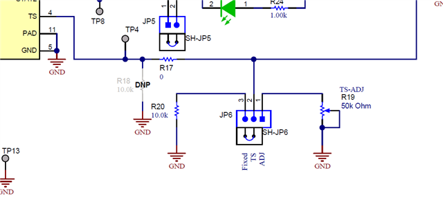
Is it due to the fact that TS is set to 0V?
In that case, I am using Quick Start Guide as an example.
I am using the Quick Start Guide as an example, but would it be correct to change the 10kΩ pull-down?
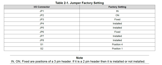
The resistance value on the development board shows 450Ω with JP6 open and JP6 2-3Pin shorted.
Please let me know if these initial values are also correct after purchasing the development board.


