This thread has been locked.

If you have a related question, please click the "Ask a related question" button in the top right corner. The newly created question will be automatically linked to this question.

LM25184: Adding Current Limiting to this part?

Part Number: LM25184
Other Parts Discussed in Thread: LM3102, LMP8646, TL431

Hello,

What's the lowest-parts-count way to add current limiting to the LM25184 standard circuit?

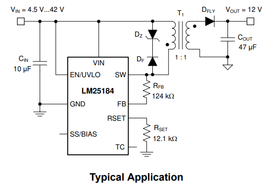
I don't want to eliminate the existing voltage regulation. I want voltage regulation plus current limiting. 

This TI video describes use of LMP8646 with an LM3102 charging a super-capacitor:

https://youtu.be/wsZOzGRtZ4g

Would the LMP8646 work with the LM25184?

Is it the lowest-parts-count method?

Thx

  • Hi Johny,

    I deleted my post that was the answer, and it looks like it deleted your post.

    I'll look into it.

    Thanks,
    Andrew

  • Hi Johny,

    I don't believe the LMP8646 will work with the way LM25481 is sampling the feedback voltage. The device samples the feedback voltage during the switching cycle when the secondary output current reaches 0. This unfortunately doesn't function with how LMP8646 is used in the video you posted.

    Because of the minimum amount of pins on the LM25481, you are limited to the internal current limiting mechanism.

    Thanks,

    Andrew

  • Can you describe the behavior of the internal current limiting in terms of continuous load?

  • Hello,

    This section talks about regular operation, and how the device will switch normally:

    This section describes what happens if the output drops below the regulation level, and the device hits the peak output of the internal FET:

    Does this answer your question?

    Thanks,

    Andrew

  • Would a current limiter on the secondary side confuse the regulator?

    Can this regulator power multiple transformers, each supplying a separate galvanically isolated load?

    If i put current limiters on each secondary, and the loads are drawing different amounts of current, will that confuse the SMPS?

  • Generally I don't think it's advisable to have 1 FETs powering multiple magnetics. I think what you might be looking for is the fly-buck topology, but one of the loads isn't galvanically isolated. Multiple sets of secondary windings is potentially more preferable.

    Also The feedback resistor network isn't setting a voltage, but rather feeding a current (section 7.3.3). So, something like LMP8646 won't be helpful for this device. I'm not sure what you plan on using for a current limiter.

    One way a colleague was suggesting using a current limiter and logic to switch the enable pin on and off as an alternative to the internal current limiter of the device.

     Thanks,
    Andrew

  • I don't think it's advisable to have 1 FETs powering multiple magnetics

    Why?

    This arrangement on the LM25184 output was recommended by an EE. Tho i'm not sure these outputs are galvanically isolated from each other.
    They appear to share grounds. 

    fly-buck topology, but one of the loads isn't galvanically isolated

    Which one?

    Multiple sets of secondary windings is potentially more preferable.

    Why?

    not sure what you plan on using for a current limiter.

    Could be an LDO, could be TL431, could be CLD.

    www.bristolwatch.com/.../TL431A3.htm

    https://www.centralsemi.com/files/manager/Engineering/Whitepapers/Boosting_the_CLD.pdf

    current limiter and logic to switch the enable pin on and off

    But that that would limit current of the regulator output, not individual secondaries, correct?

    thx!

  • Hi Johny,

    Here's the flybuck topology.

    Here's a topology with multiple windings

    This arrangement on the LM25184 output was recommended by an EE. Tho i'm not sure these outputs are galvanically isolated from each other.
    They appear to share grounds. 

    Could you link the source on this for me to review?

    I'll discuss with my team with the other points.

    Thanks,

    Andrew

  • Could you link the source on this for me to review?

    I'm sorry, it was a personal recommendation. No public source. 

    I think to obtain galvanic iso between series trafos, we just need to remove those common ground connections.

    EDIT: Yes, confirmed by the other EE. The secondary grounds should not be connected to ea other.

    Here's the flybuck topology.

    That looks similar to the LM2584 circuit. 

  • Hi Johny,

    The main reason why I wouldn't mess around too much with topologies (2 transformers in series or parallel) other than the recommended ones is because the device is not optimized to have good control loop stability with them. I would triple check the spectrum analyzer bode plot when you verify your design. 

    For this image is the LM25184 on the left or the right? It might theoretically be possible, but it's up to you to verify the design works.

    Could be an LDO, could be TL431, could be CLD.

    I'm not sure how any of these will provide the on-the-fly current limiting you are requesting. Remember that you also have to level shift the control signal to galvanically isolated control topologies which will require additional circuitry. I'm not sure how this is advantageous over using 2 separate LM25184's for your loads and controlling them with the EN pin. That requires no level shifting or current limiting at the load.

    Thanks,

    Andrew