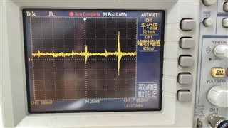
We have two backlights, old and new, with the same driving conditions,
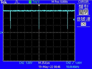
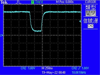
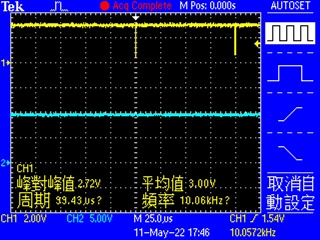
When using the old backlight, the brightness can be controlled normally by PWM (PWM frequency is 10KHz),
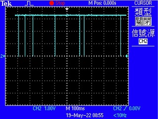
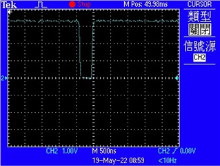
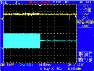
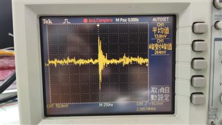
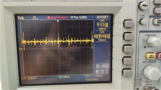
but using the new backlight, the PWM doesn't work properly.
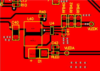
The schematic diagram is as follow:
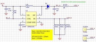
What could be the reason for this?