Because of the holidays, TI E2E™ design support forum responses will be delayed from Dec. 25 through Jan. 2. Thank you for your patience.

This thread has been locked.

If you have a related question, please click the "Ask a related question" button in the top right corner. The newly created question will be automatically linked to this question.

Fast Charging solution AND USB-pass through for Li-Ion Battery Using USB-C

Other Parts Discussed in Thread: BQ25798, BQ25895

Hi,

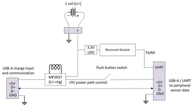
Here is a block diagram of our current system, which is sort of a "USB 2.0 pass through" PCB with power path control and bluetooth / UART.  USB data passed through and we current charge <500mA.  We'd like to improve the system and charge at 3A (15W), replacing the USB-A input connector with USB-C.  Note that the MP2637 supplies 5V from the charger input when connected, and then 5V from the Li+ cell (boosted) when the charger input is disconnected.  Also note that there is a mechanical switch that turns on the sensor data peripheral, so the D+/D- lines are not currently active until power is switched using the mechanical switch.

Do you have suggestions on how to improve our current system using TI parts to achieve 15W charge power?
  • HI Erik,

    The closest fit is BQ25798 running in backup mode but it is host controlled not standalone.  The PMID pin would be the used as SYS in your application.  You will also need a method (another IC?) to interface with the USB-C CCx lines to increase the output current to 3A.

    Regards,

    Jeff

  • HI Eric,

    Another, slightly older option is BQ25895 but it is also host controlled.

    Regards,

    Jeff

  • Hi Jeff, thank you for the reply.  We have a host available with I2C, so that will work.  Just curious if the BQ25798 can handle 5A of charge current why would I need another IC?  Or I guess you mean I need to negotiate with the host over D+/D- lines?  Which TI chip can do that?  And how can I do that but still have communication with our USB pass through peripheral?

  • USB-C doesn't use D+/D- to communicate, only CC1/2 lines.  The BQ25xxx parts do not have CC1/2 lines.  So, you will need a method to communicate only the CC1/2 lines to get the USB-C to output 3A.

    Regards,

    Jeff  

  • ah, okay, that's the part I was missing, thanks.

  • Jeff, one thing I'm confused on is that the datasheet for the BQ25798 says "To support fast charging using adjustable high voltage adapter, the device provides D+/D- handshake. The device is compliant with USB 2.0 and USB 3.0 power delivery specification with input current and voltage regulation."

    So why are they talking about D+/D- if all I need to do technically is manage CC1/2 lines from a USB C connector?  Is this for a different type of USB connector (micro for example)?  Just for my understanding, if I went this route, is it okay that the BQ25798 connects to my pass through peripheral D+/D- lines for normal communication?  Is there a bus conflict?

  • Erik,

    The BQ25798 only uses the D+/D- at first power up to set the charger's input current limit so that it matches that the output current of its power source.   Then the D+/D- lines go high Z.  USB-C is backward capable with USB2.0/3.0 through D+/D- but uses CC1/2 to negotiate higher than 1.5A output current.

    Regards,

    Jeff

  • Okay, so based on my research, I will pull CC1/2 high with 10kohm to 5V to negotiate 3A with a USB-C power source if its connected.  To know if its connected I will have my host monitor the voltage at CC1/2 to make sure it drops to the right level.  If at the right voltage level, I will tell the BQ25798 (over I2C) to charge at 3A.  Is this more or less correct?  

    Thanks a lot for your help

    Erik

  • Erik,

    I am not a USB-C expert and my USB counterparts tell me that is technically not a supported method (they want to sell their USB-C communication IC) but I see other customers doing it.   

    Regards,

    Jeff