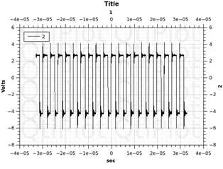
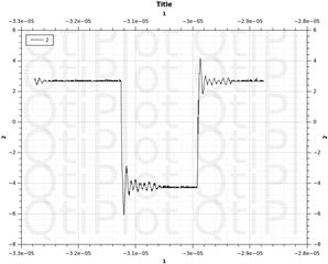
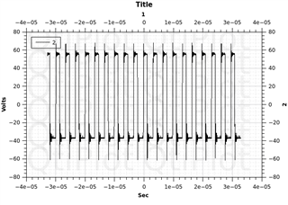
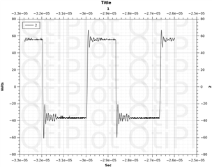
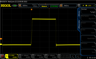
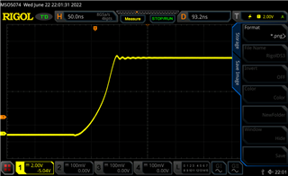
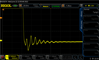
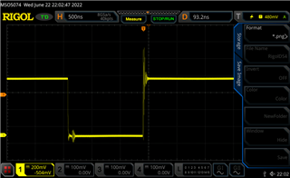
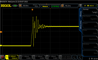
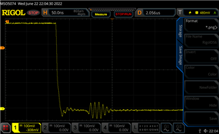
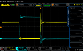
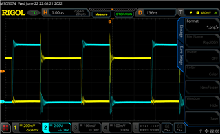
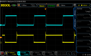
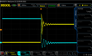
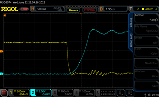
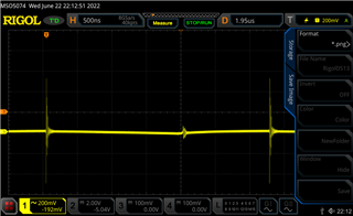
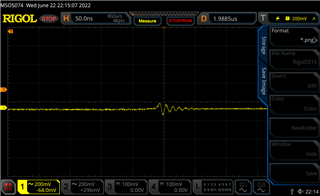
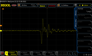
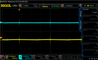
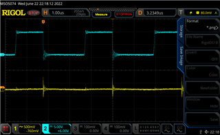
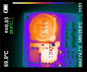
I have I problem with over temperature LM3429 and switching MOSFET and system work with efficiency above 80%. Maximal efficiency is only on 300khz (Rt=82k) on more high frequency, efficiency is very low.
Topology: buck-boost
Vin: 36V
Iout: 0.23A
MOSFET: Sir696DP
Inductor: CDRH127/LDNP-680MC SUMIDA 2.6A
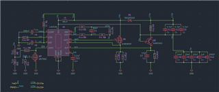
schematic:
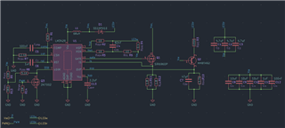
topology:
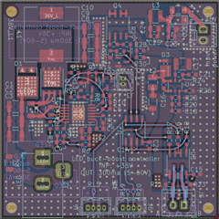
termal zones:
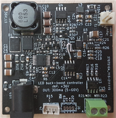
board: