- Ask a related questionWhat is a related question?A related question is a question created from another question. When the related question is created, it will be automatically linked to the original question.
This thread has been locked.
If you have a related question, please click the "Ask a related question" button in the top right corner. The newly created question will be automatically linked to this question.
Hello,
My customer has a few questions about the TPS544C25 VOUT setting.


They want to use VOUT = 0.85V without PMBus control.
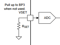
1. Output voltage by VSET
Are all of the following A and B settings available?
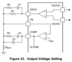
A. Rset = 15.4kohm (VOUT=0.85V) / R1=10kohm, Rbias=10Mohm (VOUT_SCALE_LOOP = 1)
B. Rset = 15.4kohm (VOUT=0.85V) / R1=10kohm, Rbias=DNI (VOUT_SCALE_LOOP = default 1)
2. Dividing resistor
2-1. Is it not possible to use a voltage divider method using R1/Rbias like the TPS544C20?
Should the loop be designed with only 1, 0.5, 0.25 ratios?
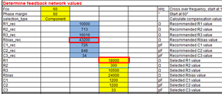
2-2. When R1=18kohm is entered in the TPS544C25_Calculator Checklist.xlsx file, the Rbias value is displayed as 43.2kohm.
Is this normal? Same value as TPS544C20.

Thank you.
JH
The internal logic that translates the VOUT_COMMAND setting to the DAC control of the reference voltage only understands VOUT_SCALE_LOOP settings of 1, 0.5, and 0.25 (Resistor divider ratios of Open, 1:1, 3:1)
While it is possible to set the output voltage to a different level by mismatching the feedback divider and VOUT_SCALE_LOOP factors, it is not recommended and there are potential issues with doing so, even when not using PMBus to set VOUT_COMMAND. In addition, adding an external resistor divider from DIFFO to FB will increase the ouptut voltage tolerance band by the accuracy of the resistors in the divider. Setting the reference voltage to the target output voltage (0.85V) and not using a FB to AGND resistor is the most accurate way to set the output voltage.