This thread has been locked.

If you have a related question, please click the "Ask a related question" button in the top right corner. The newly created question will be automatically linked to this question.

UCC27322: Output current to turn on and off the Power MOSFET

Part Number: UCC27322
Other Parts Discussed in Thread: UCC27614, UCC27624, CSD19535KTT

Hi,

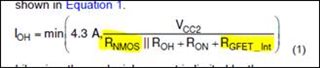
UCC27322 is used to drive MOSFET IRFP22N50A. I am interested to calculate min-max gate current required to turn on and turn off the MOSFET. 

Below is the circuit under consideration. Load current is 4A.

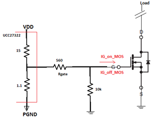
Do these resistor values need to be considered while calculating the on/ off gate current? 

Please confirm the gate current.

Also, how would the driver behave in case of overvoltage?  

  • Hi Prachi,

    Thank you for reaching out on E2E!

    MOSFETs are voltage driven and are dependent on Vgs. When the gate driver provides a voltage at the gate of the MOSFET that is above the threshold of the FET in the datasheet, the MOSFET will conduct and allow current to flow from drain to source. I will attach this Gate-Source threshold voltage (Vgs) required to turn on the MOSFET from the datasheet of IRFP22N50A.

    Also it is important that your Vgs is higher than this threshold to ensure that the MOSFET is fully conducting rather than being half-on.

    What you can calculate is your peak sink/source current. Below I will attach a TI tech note going over the peak sink and source currents of our drivers along with how to calculate IOH and IOL.

    Understanding Peak Source and Sink Current Parameters: https://www.ti.com/lit/an/slla387a/slla387a.pdf?ts=1656515442661&ref_url=https%253A%252F%252Fwww.google.com%252F

    In the case of overvoltage, if the device is subjected to parameters that go beyond what is specified in the absolute maximum ratings in the datasheet, device performance cannot be guaranteed. 

    UCC27614 is our newest single channel gate driver that is pin to pin with UCC27322. It is a 10-A Single channel driver and is much more robust in terms of handling voltage transients in comparison to UCC27322. This would be a better device to consider especially if there is a lot of noise seen. I will link the UCC27614 device page below.

    UCC27614: https://www.ti.com/product/UCC27614

    I hope this helps!

    Thank you,

    Kevin

  • Hi Kevin,

    In Prachi's system some error occured so she posted from my account.

    Thanks for attending this and for sharing the tech note too. 

    I understood and agree with your comment on MOSFET. 

    Referring to the tech note you shared, can you guide me to find RNMOS and RGFET_Int values for UCC27322 to calculate sink and source current?

    Also let me go through the new suggested part and get back to you in case of any query

  • Hello Ajay and Prachi,

    I am so sorry! I have no idea what could be causing that but I can defiantly answer your questions.

    RNMOS is the on-resistance of the N-channel MOSFET in the output stage of the driver. For some of our newer devices, we specify it in our datasheet. For example, for UCC27614 this value is 0.52 Ω. 

    For UCC27322, the value of RNMOS is not stated. However we can approximate this value as 1.5 x Rol (Output resistance low). So the RNMOS value here would be approximately 1.1Ω * 1.5 = 1.65 Ω. An FAQ goes more in depth on this. It can be found here:

    RGFET is the internal resistance of the gate. Unfortunately IRFP22N50A does not state what their internal resistance is. For example, CSD19535KTT lists Series gate resistance (RGFET) in its datasheet as 1.4Ω. 

    My colleague has written an FAQ on calculating the peak current! In this FAQ, he goes over calculating the peak current using UCC27614. This might be easier to follow along than the tech note above since UCC27322 is also a single channel driver that is pin to pin with UCC27614.

    To Summarize and make things a little easier, below I am putting the relevant pieces from the UCC27322 datasheet for you to use in your calculations.

    • RNMOS = 1.65Ω (Typical)
    • ROH = 15Ω (Typical)
    • RON/ROL = 1.1Ω (Typical)
    • RGFET = ? (You can try and contact the manufacturer and see if they can give you that Rg value. For now you can approximate it using another FETs datasheet)

    And sounds good! Would love to hear your thoughts on it!

    If you have any further questions please let me know!

    Thank you,

    Kevin