This thread has been locked.

If you have a related question, please click the "Ask a related question" button in the top right corner. The newly created question will be automatically linked to this question.

UCC28950: UCC27714EVM-551: Efficiency jump earlier seen when SR MOSFETs turned ON has suddenly disappeared

Part Number: UCC28950
Other Parts Discussed in Thread: UCC27714EVM-551,

Hello,

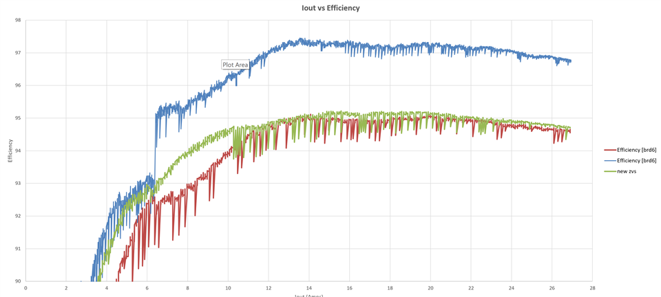
We modified the UCC27714EVM-551 for 24V output by changing transformer turns ratio and other key components voltage ratings.  The original deadtime delay settings on the eval board seem to work well, so we left them as is.  Once we got the board all working properly with our changes, we were recording a jump in efficiency from 95% to about 97%  when the SR MOSFETs turn on around 6.5A output current...which was consistent over one week of testing (see blue curve in attached plot)....  Original 26uH ZVS inductor on the board is used, which was getting up to 120deg.C with a desktop fan blowing on the board at medium speed.

We saw the primary clamp diodes were heating up to 70deg.C, so we changed to 5A fast recovery diodes (Vishay VS-5ECU06-M3) and saw they were heating up more...so, we stopped the measurement and replaced them with the original diodes (OnSemi MURS360T3G).  Now when we tested efficiency (red curve), the efficiency was worse all across and the jump in efficiency upon SR MOSFETs turning on disappeared.

We then changed the ZVS inductor to a 50uH value and saw the efficiency improve a bit (green), but much worse than the blue curve.  We are scratching our heads and haven't been able to figure out what happened.

We did try to measure the voltage drop across the SR MOSFETs...but the measurement was noisy and was transitioning from a positive voltage drop to a negative voltage drop during the time the MOSFETs were supposed to be ON.  Attached Word file shows measurement of Vds (Ch4, 465mV/div) at Iout = 4A (SR's are OFF) and at Iout=7A (SR's are ON).  Ch1 (yellow) is the corresponding gate drive signal, Ch1 is at 5V/div.  Horizontal scale at 2.5us/div.

Any tips to figure out the cause of loss in improvement in efficiency when SR's turn ON would be really helpful.

Regards,

Nitish

Q6_Vds_TIE2E.docx

  • Hello,

    The red and green curve look like the efficiency cures similar to the EVM.  However, the step that is generally seen when the SRs are turned on and off does not seem as noticable

    I wonder if you damaged the SR FETs.  I would try replacing them.

    Regards,

  • Hi Mike,

    Thank you for your response.  We did change the SR MOSFETs but did not see any change in efficiency.

    We are suspecting may have something to do with the timing when the SR's turn OFF (even though we didn't change that value when we saw the efficiency drop).  Since ADEL and ADELEF are tied to ground, I tried using the timing equations presented in SLUSA16D by setting VADELEF to zero in equation 161 to calculated REF (R8 on daughter card), but I am getting an enormous value....so, not comfortable trying that.

    Would you mind helping show how to calculate REF (R8) with ADEL and ADELEF tied to ground?

    Regards,

    Nitish

  • Hello ,

    In the equations in the data sheet for setting TABASET and TCDASET and TEFSET just set CS*KA  to zero.

    You can get shorter delay time by setting ADEL and ADELEF to 1.8 V if needed.

    Please note in these equations in the data sheet RAB, RCD and REF are assumed to be in k ohms.  

    Regards,

  • Hello Mike,

    We are unable to affect tAFSET (tBESET) by increasing R_EF (R8) on daughter control board. The intent of increasing tAFSET was to reduce Q6 body diode conduction loss.

    We increased R_EF (R8) from 56.2k (value present on UCC27714EVM-551 eval board as received) to 64.9k. We expected to see an increase in tAFSET [the time interval between Vgs-Q2 (QA per slusa16d) going low to the point where Vgs-Q6 (QF per slusa16d) goes low]....but it remained the same for corresponding load currents.

    For instance:
    For Iout = 7A, tAFSET = tBESET = 1.84us....for both R8=56.2k and R8=64.9k. The time between Vgs-Q6 going low to the point where voltage across transformer winding connected to Q6 changes polarity stayed at 760ns for both resistor values.
    For Iout = 25A, tAFSET = tBESET = 1.08us....for both R8=56.2k and R8=64.9k. The time between Vgs-Q6 going low to the point where voltage across transformer winding connected to Q6 changes polarity stayed at 1.44us.

    Any tips on reasons why changing R_EF won't change tAFSET or tBESET would be greatly appreciated (or how to increase tAFSET).

    Have a great weekend!

    Regards,

    Nitish

  • Hello,

    ADEL and ADELEF are tied to ground on the UCC277714EVM-551.  This EVM uses a fixed delay approach shorting ADEL and ADELEF to ground with R17 and R20 being zero ohms.  So your delays should not be moving with loading as you have observed.  

    If you want to use the adaptive delay you need to setup up the voltage dividers on the ADEL and ADELF pins to the CS pin.  These dividers are formed by R16, R17 and R19, R20. A good starting point is to set these dividers so ADEL is 1.8V at full load. 

    Regards,

  • Hi Mike,

    According to your post last week, when ADEL and ADELEF are tied to ground, then "In the equations in the data sheet for setting TABASET and TCDASET and TEFSET just set CS*KA  to zero."

    According to SLUSA16D, pg. 21, "If ADELEF is connected to GND, then the delay is fixed, defined only b resistor R_EF, from DELEF to GND".

    We don't want to use adaptive delay.  Per both the statements above, changing R_EF should be changing TAFSET....but it is not.  Please help.

    Regards,

    Nitish

  • Hello,

    The tAFSET delay is the delay between A turning off and F turning off.  You had mentioned that you changed resistor R8 and did not see a change in the A and F turn-on delay.  Could you double check that to see if it is correct?  

    Also the delay should not be moving with load, which your enquiry states it did.  Also it stated it did not change.  This is confusing.  Could you double check your inquiry to see if it is correct?

    Regards,

  • Hi Mike,

    Please see my responses below:

    Mike'O:  The tAFSET delay is the delay between A turning off and F turning off.  You had mentioned that you changed resistor R8 and did not see a change in the A and F turn-on delay.  Could you double check that to see if it is correct?  

    Nitish:  I understand that tAFSET is the delay between A turning off and F turning OFF.  I stated that changing R8 did not change tAFSET.  That is still correct.

    Mike'O:  Also the delay should not be moving with load, which your enquiry states it did.  Also it stated it did not change.  This is confusing.  Could you double check your inquiry to see if it is correct?

    Nitish:  I stated that for a given load, the tAFSET did not change when we changed R8 (R_EF).  I gave two load examples, Iout=7A where tAFSET was observed to be fixed at 1.84us (regardless of whether R8 was kept as 56.2k or 64.9k) and Iout=25A, where tAFSET was observed fixed at 1.08us.  This is still correct.

    Regards,

    Nitish

  • Hello,

    There should have been a 15 difference in the TAFSET delay by change R8 from 56.2k to 64.9 k ohm.

    Could you look at OUTA and OUTF directly to see directly what the turnoff delay is?  It should have change 15%. You had mentioned the delay was between 1.08 us and 1.84 us. 

    Based on the calculations, with an Ref(R8) of 56.2 k the delay should have been 110 ns.  With and R8 of 64.9k the delay should have been 126 ns.  Your delays are much larger than this an appear to be be moving with load.  They should not if ADELEF is shorted to ground.

    You might want to double check the resistors your change as well.  Because changing R8 should have had an effect on these delays.

    Regards,

  • Hi Mike,

    There is a definite disconnect between the delays I am measuring and the one predicted by eqn. 6.  Please see attached .pdf file for the tAFSET measurement at Iout=25A and the load dependency of tAFSET for Iout=7A and Iout=25A.

    It looks like Vgs-Q6 (QF) ON-time is the union (Boolean sum) of Vgs-Q2 (QA) and Vgs-Q3 (QD).

    Vgs-Q2 (QA) and Vgs-Q3 (QD) are phase shifted more for smaller load currents compared to larger load currents.  Hence, after Q2 turns OFF, for smaller load currents Q3 will turn off after a longer interval while for larger load currents Q3 will turn off after a shorter time interval, as seen for Iload = 25A above.  This makes sense, as it is the overlap between Q2 (QA) and Q3 (QD) ON-time that causes active power transfer to the load.  Hence, tAFSET should be load dependent even with a fixed delay approach....wouldn't you agree?

    Regards,

    NitishtAFSET_measure.pdf

  • Hi Nitish

    Mike is out of office today, please allow him through Friday to get back to you.

    Thank you for your patience.

    Ray

  • Hello,

    I am reviewing your waveforms presently.

    Regards,

  • Hello,

    I looked at your waveforms and they are all taken on the gates of the FETs.  Could you retake these waveforms at OUTA, OUTB, OUTE and OUTF of the UCC28950 controller?  There should not be a turnoff delay moving with load in regards to the UCC28950 if ADEL and ADELEF are tied to ground with zero ohm resistors.

    You are basing your delays on how long it takes for the FETs Vds to go low.  Even though OUT E and OUTF from the UCC28950 has gone low.  There is going to be a further delay by how long it takes the driver to pull the gate from 12V down through the miller plateau down to Vgs.  dt = dQ/Idrive 

    I think if you retake these times and look at the outputs of the UCC28950 the delays will not move with loading, if ADEL and ADELEF are shorted to ground.

    The equations for TABSET, TCDSET, TAFSET, TBESET in the data sheet describe the delay timing when ADEL and ADELEF are set to 1.8V.  When ADEL and ADELEF are grounded I believe you have to add additional 50 ns to the equations given in the data sheet.

    Regards, 

  • Hi Mike,

    I will work on that and let you know what I find.

    Regards, Nitish

  • Hi Mike,  would you mind helping clarify the following:

    1)  Is it OK to have tABSET, tCDSET fixed, while have tAFSET adjustable?

    2)  We can tie tAFSET to 1.8V for all loads (using voltage divider RAEF/RAEFHI  to VREF instead of tying to CS) and get a fixed tAFSET value.  The value obtained for tASFET in this manner would be higher than the tAFSET value obtained when RAEF is tied to ground (assuming REF is the same in both cases).

    Regards,

    Nitish

  • Hello,

    1.   Functionally you should be able to have TABSET and TCDSET fixed, while having TAFSET adjustable. In general customer's either use adaptive delay for all the delays, or they used fixed delays.  However, it does not mean that you can't make TAFSET adaptive.  So I don't see why you can't try this approach.  With all designs it is necessary to verify your design with production and worst case testing.

    2. The delays should be higher if ADEL and ADELEF pins art tied to 1.8V  Please see the test data below.

    Regards,