This thread has been locked.

If you have a related question, please click the "Ask a related question" button in the top right corner. The newly created question will be automatically linked to this question.

LM3478: Unstable COMP pin

Part Number: LM3478
Other Parts Discussed in Thread: TAS5828M

Hello,

I am using the LM3478 to convert a 2-cell LiPo battery (7.4V nominal) to a dynamic voltage rail for the TAS5828M audio amplifier using its Hybrid PWM Feedback feature to modulate the LM3478 FB pin. I hear audible noise from the boost when this feature is enabled. This led me to investigate my compensation network and I saw that the voltage was not stable during operation. Even in steady-state conditions where the audio amplifier was not modulating the FB pin, the COMP pin goes to its rail every second or so, which corresponds with the timing of clicks I hear. Could I request some help to validate that my compensation is appropriate? 

Thanks and regards,

Craig

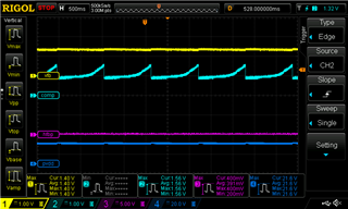
The image above shows the FB pin on CH1, the COMP pin on CH2, the amplifier Hybrid PWM FB pin on CH3, and the boost output voltage on CH4 while no music is being played.

The image above shows typical behavior of the system while playing audio

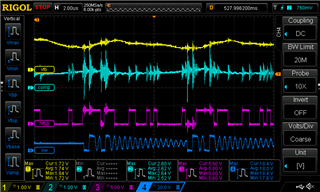
In this image, the SW node is shown on CH4 instead of boost output voltage

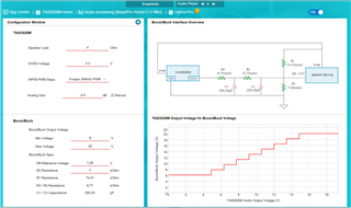
This shows the output of TI's PurePath Console 3 tool where the Hybrid Feedback feature is configured.

TAS5828M.pdf

Schematics attached here

  • Hi Craig,

    Thank you for using E2E forums, could you please tell me what are your design specs? Vin (max, min, typical), Vout, Iout and Fsw.

    Thank you

    BR,

    Haroon

  • Hi Haroon,

    Our VIN is 6V min, 7.4V nominal, 8.4V max. Our VOUT is dynamically controlled by the TAS5828M audio amp. The min VOUT is equal to VIN, the max VOUT is equal to 20V, but the nominal VOUT of the boost is 14.5V. Our switching frequency is 500 kHz and the maximum output current is 2.5A.

    Thanks and regards,

    Craig

  • Hi Craig,

    Thank you for your reply. I am not familiar with TAS5828M audio amplifier and its Hybrid PWM Feedback feature so I do not know that part of the schematics, but I can tell you that your compensation setup will give you a Fco of 2.62kHz (that is a bit too low) and PMco 101.7(this seems a bit too large). I would suggest using Rcomp of 7.6k, Ccomp 5.7nF and Chf of 0.6 nF, this will result in Fco of 7 kHz and PMco of 66.7 degrees.

    Could you please explain what seems to be the problem? what I am understanding is that there is something wrong with your COMP pin waveform, is that correct?

    Also your Cin and Cout seems to be too small, if you are seeing a lot of noise that might be due to that recommended Cin would be 220 uF and Cout 180 uF.

    BR,

    Haroon

  • Hi Craig,

    As I have not heard back from you, I will close this thread. If you have any further questions regarding this matter, you can open another thread on E2E.

    BR,

    Haroon