This thread has been locked.

If you have a related question, please click the "Ask a related question" button in the top right corner. The newly created question will be automatically linked to this question.

BQ25790: Question about BQ25790

Part Number: BQ25790
Other Parts Discussed in Thread: BQ24179

Hello:

Please help confirm whether there is a problem with this charging circuit.

The problem we are facing now is that this charging circuit affects the USB circuit of the system, which is a little difficult to understand.

8 CPU IO.pdf

19 charger.pdf

  • Hi Jimmy,

    The schematic looks okay.  I need more info What is the issue?  Is the charger crashing the USB bus at power up?  If so, then using the ILIM_HIZ resistor divider to lower input current limit.  Is the charger's D+/D- communication for the first 2 seconds after power up causing issues for other D+/D- comms?  If so, then delay D+/D- comms from other devices until after the first 2 seconds. 

    Regards,

    Jeff

  • Hi Jeff:

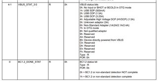
    1. From which register to identify whether there is external USB charging;

    2. The charging chip BQ25790 cannot recognize the type of charger;

  • Hi Jimmy,

    the bits below from REG0x1C report the result or failure of USB detection:

    Regards,

    Jeff

  • Hi Jeff:

    Two questions need your help:

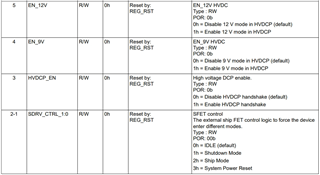
    1. How to use 9V HVDC / 12 HVDC mode? Whether the chip automatically detects the voltage to set or requires CPU to set;

    2. Function of external ship FET: in the case of ship mode, which circuits work and which do not work.

  • Hi Jimmy,

    Regarding 1, the EN_12V and EN_9V and HVDCP_EN bits must be preset by the CPU in order for the charger to detect such adapters.  Those bits are not set by default.

    Regarding 2, in ship mode, I2C still works.  But since you can't enter ship mode if power is present at VBUS, the IC is essentially in HiZ mode, which means most circuits are in lowest power mode.

    Regards,

    Jeff  

  • Hi Jeff:

    Thank you. Now we find another problem, that is, although the charging current and input current I set are both 3a, the actual current measured from the charging line is only about 1.3A.

    What is the possible reason for this?

  • Hi Jimmy,

    Is the EN_ILIM bit = 1?  If so, then the input current is clamped to the value set per the ILIM_HIZ resistor divider.

    Regards,

    Jeff

  • Hi Jeff:

    Yes, the bit default is 1. Now I set it to 0, and the current can be increased to about 1.9a, but it still cannot reach the 3A output of the charger.

    I also set the maximum charging current and input current of 3a in the register.

    Is there any other place to control?

    Five kinds of chargers and three charging wires are tried. It is found that different combinations have different results. Some combinations will fail to recognize the charger type. Even if the DCP charger type is recognized, the charging current will be different. Some can reach 2.8A, and some are only 1.5A.

    There is a USB cable inserted into the computer, which cannot be recognized as a U disk. Five kinds of charging heads are recognized as SDP, with a 500mA charging current.

  • Hi Jimmy,

    What do the status and fault registers report?  Is the charger in VINDPM, meaning the input voltage is dipping to the VINDPM threshold and then reducing input current?  Is the charger in thermal regulation?  

    Regards,

    Jeff

  • Hi Jeff:

    Here are the values of registers printed by two different chargers.

    There were some problems before. Customer use BQ24179

    Charger A:

    -ibus_adc=1271000

    -get ichg_curr=3000000

    -input current limit=3000000

    -input_v_lim=0x24

    -chrg_stat_0=0x4f

    -chrg_stat_1=0x67

    -chrg_stat_2=0x1

    -chrg_stat_3=0x0

    -chrg_stat_4=0x0

    -chrg_flag_0=0x0

    -chrg_flag_1=0x0

    -chrg_flag_2=0x0

    -chrg_flag_3=0x0

    -chrg_ctrl_0=0xa2

    -chrg_ctrl_0=0xa2

    -chrg_ctrl_1=0x80

    -chrg_ctrl_2=0x40

    -chrg_ctrl_3=0x12

    -chrg_ctrl_4=0x0

    -chrg_ctrl_5=0x14

    -fault_status_0=0x0

    -fault_status_1=0x0

    -fault_flag_0=0x0

    -fault_flag_1=0x0

    -ibat_adc=484000

    -ibus_adc=1281000


    Charger B

    get ichg_curr=3000000

    input current limit=3000000

    input_v_lim=0x24

    chrg_stat_0=0x4f

    chrg_stat_1=0x67

    chrg_stat_2=0x1

    chrg_stat_3=0x0

    chrg_stat_4=0x0

    chrg_flag_0=0x0

    chrg_flag_1=0x0

    chrg_flag_2=0x0

    chrg_flag_3=0x0

    chrg_ctrl_0=0xa2

    chrg_ctrl_0=0xa2

    chrg_ctrl_1=0x80

    chrg_ctrl_2=0x40

    chrg_ctrl_3=0x12

    chrg_ctrl_4=0x0

    chrg_ctrl_5=0x14

    fault_status_0=0x0

    fault_status_1=0x0

    fault_flag_0=0x0

    fault_flag_1=0x0

    ibat_adc=1016000

    ibus_adc=2672000

  • Hi Jimmy,

    Both chargers are reporting VINDPM, which means the input current is pulling the voltage at VBUS down to the VINDPM threshold.  If input_v_ilim above =0x24 is that threshold, then the input voltage is being pulled down to 3.6V.  Is the connection from power supply to charger, highly resistive?

    Regards,

    Jeff