This thread has been locked.

If you have a related question, please click the "Ask a related question" button in the top right corner. The newly created question will be automatically linked to this question.

TPS543C20: Bypass capacitor value of remote sensing

Part Number: TPS543C20

Hello,

My customer is using the TPS543C20 with the conditions below.

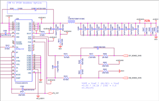
    - VIN = 12V, VOUT = 0.852, IOUT = 32A, FSW = 500KHz

Could you please suggest the optimal values for the C499 and C932 in the direction that the output voltage is as stable as possible?

Thank you.

JH

  • Hello JH, 

    We are looking into this. We should respond in a couple days. 

    Thanks! 

    Tahar 

  • Hi JH,

    For the feed forward capacitor (C932),  please follow the guidelines below to estimate an optimal value:
    1. Use the attached Bode Plot Calculator to estimate the crossover frequency of your design without a feed forward capacitor. I filled most of this out for your case already, however, your pinstrap selection for RAMP is required to get a proper estimation of cross over frequency

    1638.TPS543C20 Bode Plot Design Tool.xlsx
    2. Use the calculated cross over frequency (fco) and your resistor divider network to estimate the optimal Cff (R1 is Rtop and R2 is Rbot)

    For C499, it is recommended that the corner frequency of the RC filter be at least 2-3x higher than fsw to avoid having the filter impact the phase margin negatively. In this case, if Fc = 1500kHz = 1/(2pi*RC), calculating this out to solve for C gives a value of 36pF

    Best regards,
    Britton

  • Hi Britton,

    Thanks for your reply.

    I can see a link error in the middle of answer #2 above. Is this a formula to calculate Cff?

    Thank you.

    JH

  • Hi JH,

    That's strange that the image is not showing up on your end, but yes that is an equation for Cff.

    The equation is as follows: Cff = (1/(2pi*fco))*sqrt((1/R1)(1/R1+1/R2)). Please pay close attention to the parentheses 

    Best regards,
    Britton