This thread has been locked.

If you have a related question, please click the "Ask a related question" button in the top right corner. The newly created question will be automatically linked to this question.

UCC28061: UCC28061 Enquiries

Part Number: UCC28061

Hi Team,

Previously I have already posted a similar thread to enquire about UCC28061(Thread ID: 1105457). I have decided to open another new thread because there is a few more enquiries from my customers.

Could you guide us on the questions below:

  • Why do the two gate outputs work at different frequencies (GDA = 120KHz and GDB = 167.4KHz)?
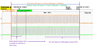
  • Why are the two gates not running 180° out of phase.
  • Why are the two gates always turn on at the same time during start up?
  • The PFC output can't be regulated at no load. But can be regulated under light load.
  • Why are the comp pin unstable at no-load?
  • Why the comp pin going high (about 4.9V) for about 400ms after AC off. if ac recycle within 400 mS, then the soft start cannot working.
  • How Soft Start Works
  • How to set the maximum on duration(Ton-max)?
  • How to set the maximum and minimum operating frequency?

Attached is the waveforms for reference.

UCC28061_Waveform_TI.xlsx

Thank you very much for your constant support!

Best Regards,

Ernest

  • Hi Ernest,

    Thanks for the query. This has been assigned to a product expert, please allow one or two business days for a response.

    Regards,

    Harish

  • 1 The frequency differences are temporary as the internal phase-locked loop adjusts the on-times to drive the two phases toward 180-degrees phase-shift. If you look over a longer period, the frequencies are the same (See expanded waveform below.)

    2 The waveforms were examined only at the beginning where they are in phase.  Later in time they move out of phase toward 180-degree interleaving. (See expanded waveform below.)

    3 That is the way the IC is designed.  They always start in-phase at start-up or restart after a fault, then move apart toward 180 degrees.

    4 This is not a normal case. Something is wrong with this design’s compensation.  Normally, the PFC output is stable and regulated even at no load.

    5 Something is wrong with this design.  Need the schematic diagram to help discover the problem.

    6 When AC goes off, no power is boosted to the output, but output load still runs and pulls down Vout. This drives the error amp to saturation (COMP = ~5Vmax).
        VDD to UCC28061 falls below UVLO threshold after ~440ms, then COMP falls to 0V.
        If AC comes back before VDD falls, then there is no soft-start because COMP = ~5V.

    7 At first power-on, until VDD first comes up above the turn-on threshold, COMP is held to 0V.  After VDD is above UVLO, COMP is released and switching starts. 
        COMP rises slowly due to limited charge current into capacitors on COMP.   This results in slow increase in current and soft-start.

    8 Minimum frequency is set by choice of boost inductance.  Follow design procedure.  See equation (8) in datasheet.
       Maximum frequency is set by minimum period timer, set by TSET resistor. See equation (6) in datasheet.

  • Hi Ray,

    As always, thank you for your strong support.

    Here are the response I receive from my customers.

    For items 4 and 5, we can share the schematics with you, via email.

    For item 6, we had a problem with the PFC choke saturating the power cycle within 440ms. Do you have any solution?

    For item 8, how do I set the maximum on-time (Ton-max)?

  • Hi Harish, 

    thank you for your help. 

    follow up on previous topic 

    For items 4 and 5, we can share the schematics with you via email. You need confidentiality. Because it is our product confidential information. 

    For item 6, we had a problem with the PFC choke saturating the power cycle within 440ms. Do you have any solution?

    For item 8, how do I set the maximum on-time (Ton-max)?

     Best Regards,

    Roger

  • Hi Roger, please email your schematics to me for support on items 4,5 & 6. They will be handled as Confidential. Ernest can help you with that.

    With the issues you're having, I don't think that increasing Ton_max is the solution. However, if you still want to do so, you can lower Rs which will increase the peak current limit and thereby extend on time.

    Regards,

    Ray

  • Hi Roger,

    I am closing this thread as the schematics have been sent through email and we're picking this up from there.

    Regards,

    Ray

  • Thanks a lot Ray. Very helpful of you.