This thread has been locked.

If you have a related question, please click the "Ask a related question" button in the top right corner. The newly created question will be automatically linked to this question.

BQ28Z610EVM-532: How to configure Battery pack of 2s with BQ28z610..?

Part Number: BQ28Z610EVM-532
Other Parts Discussed in Thread: EV2400, , BQSTUDIO, BQ28Z610, BQ34Z100

Hello TI, 

I am using BQ28Z610EVM-532, EV2400 for evaluation and Battery pack is UB26650-7.2V-5000mAh

UB26650-7.2V-5000mAh battery pack have Inbuilt Short circuit protection circuit, pack have two 26650 cell  which connected in series, have only 2 battery connection which is Pack+ and Pack-.

Battery Pack,

Nominal voltage- 7.4V 

Charging voltage- 8.4V

Capacity- 5000mAh 

UB26650.pdf

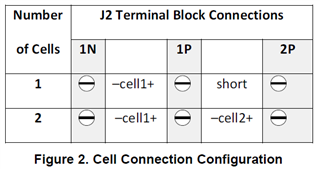
Made battery pack connection is 1S -
1. Pack+ connected to 2P (Shorted 2P & 1P)
2. Pack- connected to 1N (Shorted 2P & 1P)
  

1. BQ28Z610EVM-532 can support UB26650-7.2V-5000mAh battery pack..?

2.When release S1 from BQ28Z610EVM-532 then BQstudio is disconnected, In this case charger is not present.

3. When charger and battery is present, then also it's release communication and reconnect again, what is issue and how i can remove ..?(I attach Data memory configuration  UB26650.gg.csv )

3. Facing issue to Update FD, FC, TD, TC as per the battery pack, error message (Value is beyond maximum value defined for parameter)
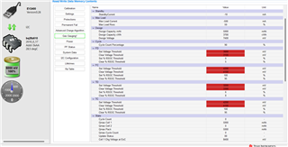
We need help to configure BQ28z610 for my battery pack.

Thank, 

Rahul

  • Hello Rahul,

    I have assigned someone to take a look at this by the end of today.

    Sincerely,

    Wyatt Keller

  • Hello Rahul,

    The main root of your issues is that you are connecting your 2 cell battery like a 1 cell
    battery in the EVM. This is causing the gauge to read larger voltages then the gauge is expecting
    and possibly damage the EVM.

    If it is possible, are you able to create a test point connection between cell 1 and cell 2 in the
    battery pack? If so, then you should connect Pack+ to 2P, the test point between cell 1 and cell 2
    to 1P and Pack- to 1N.

    If you are unable to create this test point then the BQ28Z610 EVM will not work for your setup. I
    would recommend using the BQ34Z100 EVM as this gauge does not require individual connections to
    each cell in the battery pack.

    Sincerely,
    Nick

  • Hi Nick, If follow (connect Pack+ to 2P, the test point between cell 1 and cell 2
    to 1P and Pack- to 1N) what about 3. Facing issue to Update FD, FC, TD, TC as per the battery pack, error message (Value is beyond maximum value defined for parameter)..?

  • Hello Rahul,

    What specific value are you trying to set for these parameters?

    For FD, FC, TD and TC, you would set these values in accordance to one cell.
    So for example, according to your datasheet you would set "FC set voltage threshold" to
    4200 mV since the charge cut-off voltage for one cell is 4.2V.

    Sincerely,
    Nick

  • Hello Nick,

     But Battery parameters not showing correctly, can you please share what data memory configuration i need set for my Battery pack ..?

  • Hello Rahul,

    Can you send me a picture of the battery parameters not showing correctly?

    I would recommend setting the following parameters:

    • Gas Gauging:
      • Current Thresholds:
        • Dsg Current Threshold 
        • Chr Current Threshold 
      • Design
        • Design Capacity mAh
        • Design Capacity cWh
        • Design Voltage
        • IT Config:
          • Term Voltage
        • Advanced Charge Algorithm:
          • Termination Config:
            • Charge Term Taper Current 
            • Quit Current 

        Sincerely,
        Nick

      • Hello Nick,

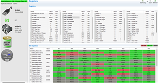
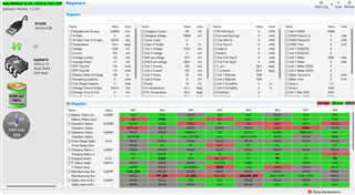
        There is issue only at Battery voltage, It's shows only single cell battery voltage (4V), expected Voltage for 2S (8V)..?

        Once this fix, i will share picture for other parameters. (Note- Other parameters showing correctly)

        Thanks, 

          Rahul

      • Hello Rahul,

        This could be caused because your gauge may be programmed for 1 cell instead of 2 cells. 

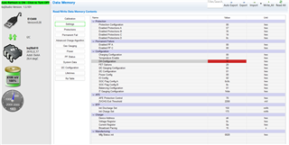
        To check this setting go to Data Memory, then go to Settings. Then under Settings, go to Configuration and then click on "DA Configuration".

        Check Bit 0 of this register. If the bit is low, then the gauge is configured for 1 cell. If the bit is high then the gauge is configured for 2 cells. 

        Setting this bit to high should fix your problem.

        Sincerely,

        Nick

      • Hi Nick, 

        Your shared image is not clear, I follow your instruction and set DA configuration bit0= 0 to Bit0=1 but there is no change in battery voltage
        Please check  my Data Memory setting UB26650_28072022.gg.csv and BQstudio dashboard 

        Thanks, 

        Rahul

      • Hello Rahul,

        Did you send me the gg file that reflect the changes after changing that bit?
        I checked the gg file and I saw that the CC0 bit is still set to low in the DA Configuration register.
        I would try setting this bit high again.

        Sincerely,
        Nick

      • Hello Nick, 

        Please check attachment


        UB26650_01082022.gg.csv

        No any change in battery detection, please check.

        thanks, 

        Rahul 

      • Hello Rahul, 

        Can you send me a picture of your test set up, showing the physical connections to the EVM?

        Also, you can test your evaluation board without your battery connected to the evaluation board. To do this you can set up a voltage divider using resistors. This process is outlined in section 2 of the TRM for the bq28z610EVM.

        Sincerely,

        Nick