This thread has been locked.

If you have a related question, please click the "Ask a related question" button in the top right corner. The newly created question will be automatically linked to this question.

LT1054: Heating issue

Part Number: LT1054

Hi,

I am using LT1054IDW device to generate -5V from 10V Buck converter as shown below.

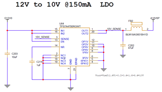
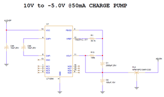
The issue is i am getting 10V output at LDO but not able to get -5V at Charge pump output and LT1054 is getting heated up.

Independently if i apply 10 V to charge pump, i am getting -5V and not getting heated.

1. What might be the reason for heat up?

2.what is solution to resolve the issue? or anything wrong design?

Thanks and Regards,

Pedaiah G.

  • Chargepump_LT1054.pdf

    Hi,

    Please find the circuit

    Regards,

    Pedaiah H

  • Hello Pedaiah,

    Thanks for reaching out to us via e2e.
    I want to apologize for the late reply. Your question has been overlooked due to a transition of responsibilities.

    It seems that the charge pump cannot get enough current from the LDO. That's why it is working properly when connected to a lab supply.

    For a charge pump the capacitor on the input side should always be bigger than the one on the output.
    Please use a bigger capacitor there.
    Also, the ferrite bead is limiting the (peak) current.
    Please also try putting a short across the bead to see if this makes it work.

    Best regards,
    Harry

  • Dear Harry,

    Thanks for the reply.

    As per your suggestion, we conducted following experiments.

    1. We have removed ferrite bead and put short across bead.

          a) Charge pump output without load = -5V.

          b) Charge pump output with load (50mA) = 1.23V and Charge pump is getting heated.

    2. We have removed ferrite bead, put short across bead and replaced input capacitance 10uF with 100uF.

         c) Charge pump output with load (50mA) = 1.23V and Charge pump is getting heated.

    3. I have Isolated LDO by removing ferrite bead and applied External +10V power supply.

         d) Charge pump output with load(50mA) = -5V.


    Queries:

    1. We have used TPS7A4700RGWT LDO to drive charge pump having output current rating of 1A. is there any constraint that LDO should not be used to  drive Charge pump?

    2. We were using charge pump in other two circuits, to generate +12V to -10V and +5V to -3.3V. we are not facing any issues w.r.t charge pump output with/without load. The only difference we could find in these circuits is, these charge pumps are driven by switching regulator. attached circuit for your reference.Chargepump_LT1054_R1.pdf

    Request you to suggest the solution to resolve the issue.


    Thanks and Regards.

    Pedaiah G.

  • Hello Pedaiah,

    Thanks for the additional information.

    It is interesting to see that the charge pump is working with the exact same capacitor values when it is connected to the switch mode supplies.

    I am not an expert of the TPS7A4700 but I could imagine that the control loop (Sense input) of that part is getting confused by the current pulses that the charge pump is drawing at the input size.
    Where exactly did you connect the sense signal (close to the LDO or close to the charge pump)?

    Does the output voltage of the LDO also go down to a lower voltage when you connect the load?

    Can you take oscilloscope screenshots of the LDO output voltage?

    A few more things to try:
    Opposite to the recommendation in the datasheet, bring the Sense feedback as close to the LDO output as possible (basically sort the OUT and the Sense pin.
    Put the ferrite bead back in.
    Increase the capacitor after the ferrite bead even more

    Best regards,
    Harry

  • Hello Harry,

    1. We Placed sense signal close to LDO. Please find the Figure 1 and Figure 2 in the attached file captured from board file  for your reference.

    2. No. The output voltage of the LDO is not going down to a lower voltage when i connect the load. The voltage reading in the multi meter and Oscilloscope is +10V at LDO Output, when I connect load to Charge pump. 

    3.Please find the Figure 3 in the attached file for your reference.

    I have connected the ferrite bead back in and increased Charge pump input capacitance to 200uF But, i am observing the same behavior as earlier with heating the charge pump and voltage of 1.21V at charge pump output.

    CHARGE PUMP DEBUGGING.pdf

    Request you to suggest the solution to resolve the issue.

    Regards,

    Pedaiah G.


  • Hello Pediah,

    Is the big 200uF capacitor placed close to the charge pump or close to the LDO?
    Which type of capacitor is that (e.g. aluminium electrolytic)?

    You wrote:
    2. We were using charge pump in other two circuits... we are not facing any issues ...The only difference we could find in these circuits is, these charge pumps are driven by switching regulator.

    Are these other designs using a similar routing with a trace around the board and a similar length?

    Thanks,
    Harry

  • Hello Harry,

    I have used Two parellel 100uF Tantulum capacitors placed close to LDO.

    The other two circuits using a different routing length.

    Please find the Figure 4 and Figure 5 in the attached file for your reference.

    CHARGE PUMP DEBUGGING_R1.pdf

    Thanks and Regards,

    Pedaiah G.

  • Sorry, I have used Two parellel 100uF Tantulum capacitors placed close to Charge pump.

    Regards,

    Prdaiah G.

  • Hello Pedaiah,

    Let's step back a bit and get back to the circuit you started with:

    1. When you supply the charge pump from the LDO, the output voltage of the charge pump is -5V when there is no load, but with 50mA load, the voltage is 1.23V.

    2. When you increase the load current slowly, when does the output voltage start to fall?

    3. When you remove the bead on the output of the LDO and use a 10V supply connected to the place where the bead was, the charge pump works properly. Is this correct?

    4. Please measure the output voltage across the output capacitor and the input voltage across the input capacitor of the charge pump when you slowly increase the output load.

    5. Please show the GND connection from the LDO to the charge pump.

    Best regards,
    Brigitte