


In many high power and high cell count battery applications, the need arises to reduce the RDSon of the load switch FETs to reduce conduction losses. The two main ways to achieve this are by adding more FETs in parallel (see this guide on the subject), or by using a FET with a lower RDSon value.
Both of these solutions increase the combined gate capacitance (Cgs) of the FETs. Because of this, the real question isn’t how many FETs the gauge can drive, but what gate capacitance it can drive at what rate.
With a fixed driver, and using the equation:
I = C * dv/dt
We know that with a fixed I value, the dv/dt value will have a linear, inversely proportional relationship with C. And since the dv is fixed, we know that dt is proportional to C. Because of this, the main issue is rise/fall time. See this section of the BQ28Z610 datasheet as an example:
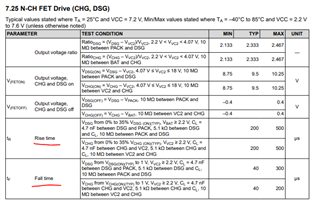
The rise and fall time are specified for a capacitance of 4.7nF. From the equation earlier, we know that if all else is kept equal, and the capacitance doubled, we would expect double the rise and fall time from what is specified.
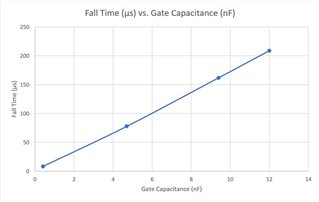
Here are some measured fall time values compared to gate capacitance. As expected, it is a linear relationship. And at the specified 4.7nF, the fall time is about 78µs, which is within the expected range.
To summarize, you can drive as many FETs in parallel as you would like. However, the rise and fall time, and therefore the time it takes to turn the FETs on and off (as well as switching losses) will increase. In addition, for very large Cgs loads, you may need to increase the PBI capacitance in order to ensure the PBI/BAT voltage does not dip from driving the FETs.
And if you decide to measure these signals yourself, be sure to measure directly on the gate of the FET, and to use a differential probe or math function to handle the floating references.
