This thread has been locked.

If you have a related question, please click the "Ask a related question" button in the top right corner. The newly created question will be automatically linked to this question.

UCC28740: UCC28740DR

Part Number: UCC28740
Other Parts Discussed in Thread: TIDM-02010, TL431

Hello TI Team 

I am Ubaida Firoz from Virtual Forest Private Limited-Bangalore (India). We are using UCC28740 for SMPS Design in Our Air-Con.

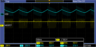
It is in board bring up stage, we are facing MOSFET & IC Burst IC while turning ON.

TI_SMPS_UCC28740DR.pdf

Please have look on schematic and guide us.

With Regards

Ubaida Firoz

Sr. Embedded Hardware Engineer

Email ID:- ubaida@virtualforest.in

Virtual Forest Private Limited

Bangalore-India

  • Hello Ubaida,

    Thank you for your interest in the UCC28740 flyback controller. 

    From a look at your schematic diagram, it appears that the primary winding polarity is backwards from the normal flyback arrangement.
    Instead, it connected as a forward-mode transformer and, depending on turns-ratio and Vpvcc, that may be applying excessive voltage to the VDD pin of IC10. 
    When IC10 fails it can also cause Q4 to fail as a consequence.

    Also, I see that the primary-side GND symbol is the same as the secondary-side GND symbol.  PCB design software will consider these to be the same network and connect them together on a circuit board.  If you design is intended to be non-isolated, then this is okay, but if you require isolation between primary and secondary sides, I recommend that you rename the primary-side GND to a different name or use a different symbol to separate the two GND networks.  

    Please check your transformer polarities and ground connections. 

    Regards,
    Ulrich

  • Hello Ulrich 

    Thanks for your reply, Problem is still there. We have taken layout guidelines and schematic from TIDM-02010 Schematic .

    What if I will use Opto-coupler with less CTR?

    Currently we are using Opto with B- Rank (CTR-130-260%) but suggested Opto in reference design (FOD817DS) is D-Rank (CTR-300-600%).

    Also we are using Wurth Transformer 750319736_rev2 same as reference design. 

    We have verified our layout with reference one, everything is matching.

    Please re-think on the schematic one more time and let us know if something we are missing.

    With Regards

    Ubaida Firoz

  • Hi Ubaida,

    We will check the schematic and revert back in a couple of days.

    Thank you

    Regards,

    Harish

  • Hello Ubaida, 

    Thank you for informing us that your design is based on the TIDM-02010.  That is helpful.  
    Comparing your transformer drawing to the TIDM schematic, I see that the MOSFET drain is connected to pin 3 of the transformer, which is the correct polarity according to the Wurth Electronik datasheet for 750318383.  (Your drawing has the polarity mark on pin 1 which is incorrect.)

    However, the TIDM schematic shows the primary ground labeled as "PGND" and the secondary ground as "GND".  These are separate networks. 
    Your schematic has the same symbol for both grounds and no name(s) shown, so it appears to be the same network. 
    I recommend, again, to check these grounds and verify that your board has separated networks. 

    Your original concern was "...MOSFET & IC Burst..." which is damage or destruction of the flyback controller and MOSFET.  I presume that that problem has not yet been corrected.  Changing the CTR of the optocoupler will not in any way prevent damage to IC10 and Q4.  Such damage is caused by some other problem with your design that has not yet been detected.  

    You mention that your transformer is 750319736_rev2, but the TIDM-02010 BoM lists 750318383 as the part number for T1.  
    I do see that 750319736 is shown in a photograph Figure 3-10 in the Design Guide document (TIDUBE5.PDF).  
    This is a discrepancy between the TIDM BoM and the Figure. I don't have access to the 750319736 datasheet, so i don't know what the winding structure looks like compared to that of 750318383.  

    I will try to involve the C2000 Industrial group who originated this TIDM design for further assistance to resolve this problem, and to clear up the discrepancies in the design.

    Regards,
    Ulrich  

  • Hello Ubaida and Ulrich, 

    Please find the notes (in red font) in the scrrenshot of suggested schematic improvement.

    TIDM02010 uses custom transfomer from Wurth, that's why part number has been changed to 750319736_rev2 but footprint and polarity remains same as 750318383. Here is the link to 750319736_rev2 trasnformer datahsheet and test data from Wurth-

    750319736r02 Spec.pdf750319736r02 Data.pdf

    As Ulrich suggested the polarity is not correct for primary winding. Secondary looks good to me. Please not that Pin 6 has dot as per datasheet. So, 15V winding polarity is also correct here. Resistor R29 and R25 has been updated to parallel combination of 2K||1K||1K (1206 package) and there is one resistor needed parallel to C25 with value of approx. 510R (0805 package). Since these are loading resistor, any value neadby is also okay. Please note that, this is non isolated design so all PGND and GND are same. In TIDM02010, these two grounds are tied with net-tie to form star connection. TIDM02010 chose flyback design with transformer for low cost step down operation. Also, if available please try using same class of optocoupler as well.

    Please try these and let us know if it resolves the issue.

    Ulrich - Please add anything that I maybe missing looking at the datahseet, schematic and notes.

    Regards,

    Sumit

  • Hi Sumit & Ulrich

    Please see VDD graph, VDD is not stable. it is fluctuating.

    secondly we are getting 5V at 15V Net.

    Sumit 

    Since you are here in Bangalore, then we can have some plan to meet and resolve, Share your contact details. Meanwhile we can discuss the cause of VDD fluctuation.

    With Regards

    Ubaida Firoz

  • Hi Harish 

    Please see the above VDD waveform, Since you are here in Bangalore, then we can have some plan to meet and resolve, Share your contact details.

    Sumit please ignore the above reply

  • Hello Ubaida, 

    Sumit has verified that the PGND and output GND are essentially the same net (non-isolated) so your common GND symbol is no problem. 
    Also, the transformer has been updated to 750319736, so the schematic polarities are no problem. 
    Please update the pre-load resistances on the Auxiliary PS outputs as Sumit indicates on his mark-up, above.

    Thank you for the screen shot of the VDD waveform.  This fluctuation is the result of repeated start-up attempts.  The UCC28740 is trying to start and is unable to complete it before VDD reaches the UVLO turn-off threshold.  Since the turns-ratio of the +15V winding to the AUX winding is 1:1 and the +15V only reaches about 5V, the AUX winding reflected voltage is unable to sustain the VDD to keep running.   

    The down-slope of the VDD lasts about 100ms and this is usually plenty of time for Vout to come up to regulation. Since the 15V Net does get up to 5V, it indicates that the MOSFET is switching.  And the yellow trace shows evidence of switching, although the sample resolution is too low at 100ms/div to show any details.  So, something is preventing the output from rising further than 5V, and this needs to be investigated and debugged.

    There could be excessive load on +15V, or excess load on any of the other outputs.  The excess load can be external to the Auxiliary PS or internal to it (such as a backwards component).  If the schematic diagram has no errors, then the physical board must have some error, such as the wrong component value(s) or incorrectly installed part, or an unwanted connection due to some manufacturing error. 

    If it is not possible to disconnect the Auxiliary PS outputs from the rest of the board, maybe you can build a new board with only the Aux PS populated and no other components.  If the Aux PS works okay by itself, then the problem is likely to be somewhere on/in the main board circuits.  If that Aux PS itself has problems, then it will be easier to systematically debug and isolate the problem without interference from the rest of the board. 

    One thing to clarify, please:  Your original post stated that "...we are facing MOSFET & IC Burst IC while turning ON."  Is this still the case? 
    Do the IC and MOSFET still fail during power-up?  Your waveform shows 1 second of start-up attempts.   Do (did) the failures happen a long time after applying power, or immediately, or only under certain specific conditions?   What has changed, to allow you to capture the waveform? 
    Since a failure is usually caused by some kind of overstress, please investigate the cycle-by-cycle waveforms on each winding and on each pin of the IC and MOSFET to ensure that they are of the correct shape, magnitude, and polarity to be expected at each moment of operation.  Or if one or more of them deviate from the expected proper shape(s).  

    Finally, here are a couple of references to help debug your Aux PS.  Although one of them is targeted for PSR controllers, there are several aspects of debug (particularly at start-up) that also apply to the UCC28740 SSR controller. 
    https://www.ti.com/lit/pdf/slua783
    https://www.ti.com/lit/pdf/sluaac5

    Regards,
    Ulrich

  • Hi TI Team 

    Thank you guys for supporting on this issue. Now issue is resolve, problem was related to different part of TL431.

    Harmeet From TI helped me to resolved it.

    With Regards

    Ubaida Firoz