Hello TI experts,
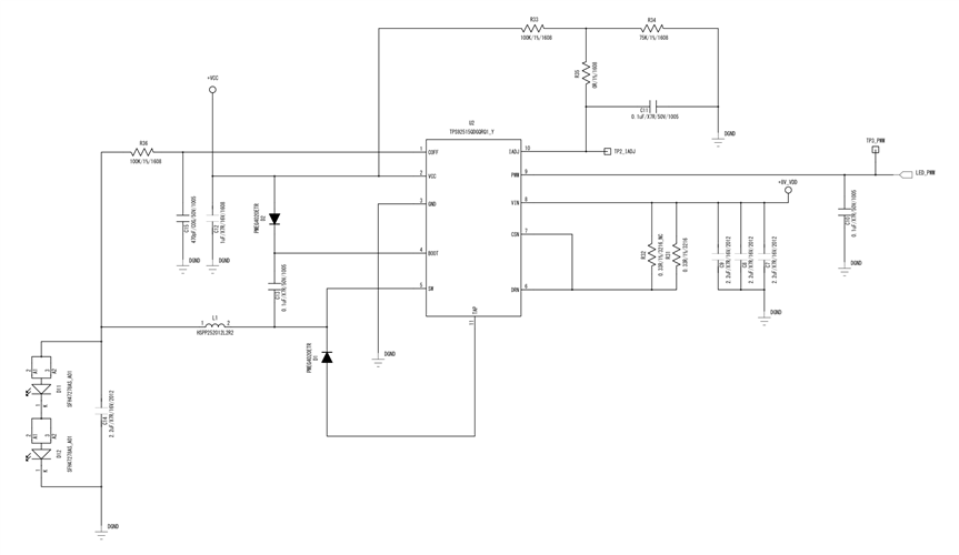
My customer drew their first schematic with TPS92515QDGQTQ1. Could you review the schematic?

- Vin: 8V
- Vout: 2.8V
- Output Current: 2A
- 2 LEDs will used. (Forward Voltage 2.5V, Total Power 1340mW )
Best regards,
Chase
This thread has been locked.
If you have a related question, please click the "Ask a related question" button in the top right corner. The newly created question will be automatically linked to this question.
Hello TI experts,
My customer drew their first schematic with TPS92515QDGQTQ1. Could you review the schematic?

- Vin: 8V
- Vout: 2.8V
- Output Current: 2A
- 2 LEDs will used. (Forward Voltage 2.5V, Total Power 1340mW )
Best regards,
Chase
Hello Chase,
Can you give me the Vin range? What is the desired ripple?10%, 20%, 40%???? Is there a desired switching frequency? Also, I can not read the component values. Please give a .pdf or something with better resolution. The connections look correct, but I can't do calculations to verify correct values. Have you gone through the design calculations outlined in the datasheet? I don't see your calculations here.
-fhoude
Dear fhoude,
Thank you for your support.
Here is the design calculator and latest schematic. Please give me some advice about it.
- Input voltage is 8V constant. it is from POC filter.
- Desired ripple is 10%.
Best regards,
Chase
Hello Chase,
I think you entered all the information correctly in the spreadsheet. I was able to look at your schematic and look up parts. Most everything looks good.
-fhoude
Dear fhoude,
Thank you for your support.
I got feedbacks from my customer, here are some questions.
- We will check D1 in 1st PCB sample. <- done.
- We will re-check the inductor with over 2A saturation current. <- done.
- We will check it in 1st PCB. <- done.
- Actually R36 is already decided in the reference (which made from other customer, and they drew their schematic almost same as this reference.)
the value was 0.33 ohm in that reference, but they could not find that value with design calculator. Could you help me about this for finding 0.33 ohm or other right value?
and here is another question.
- they set output voltage as 2.8V, and they measured real value of it on PCB (L1.1) it is about 5V, and each LEDs (in series) had 2.8V each. We thought that each LEDs would have 1.4V because output voltage is 2.8V and use 2 LEDs. Is it right operation?
I attach a PDF review for your convenience.
Best regards,
Chase
Hello Chase,
I don't understand why you can't find a 0.33 ohm resistor. This is readily available. for example:
https://www.digikey.com/en/products/detail/te-connectivity-passive-product/TL3AR033F/3673492
I don't know what they are using for LEDs, but there should be a Vf vs Current curve. Look on the curve to see the Vf at the constant current setpoint you set for the 515. That should show you what Vf (output voltage) you should expect for that condition. Where did you get your assessment from? Why 1.4V???? Output of this converter is a constant current source. The voltage is a function of the Vf of the diode at that current.
-fhoude