Other Parts Discussed in Thread: TPS2491, TPS2490,
Hi.
2 months ago I designed with TPS2491, below is the link for the post regarding TPS2491 design in TI forum:
We will use a hot swap controller as a high voltage type P transistor output, fully protected (surge, short, reverse polarity, over-current), the basic scheme is shown below, this scheme is also shown in the topic of the link above.
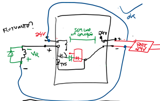
But TPS2491 and even TPS2490 are in strong shortage in the IC market. The PCB/PCBA supplier of our company recommended to replace it by LM5069, because this one, according them, is still well available in the market, so I will do this. I've already changed the schematic, tried the PCB layout again, and PCB layout with LM5069 I have already checked that its ok for component placement and routing.
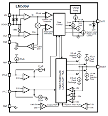
My new schematic based on LM5069:
My calculations until now are for Rsense and Ctimer, shown below, do you see any error with them?
It is missing only to calculate the Rpower, which I'm having difficult, actually I did not understood well the meaning of that power limiting value and how to calculate the resistor Rpower correctly. With a 18mR Rsense and considering the typical voltage of Vsense (55mV), the typical value for current limiting is around 3A, and that's what we need for this design (estimated). The nominal system supply voltage is 24V (those industrial power supplies), but it should be considered 36V at maximum, in a worst case. I can say that with a 24V nominal supply and 3A load current, this is around 72W, is that 72W maximum power that the LM5069 should be designed to limit? I'm needing help to calculate the resistor connected at pin 7 (PWR) of LM5069. Could you help please? I'm a little in a hurry, is there a fast and easy way to calculate this resistor for our case?
Please note that for our case, the loads are only resistive or inductive, like solenoids.
CALCULATIONS:
*************** Rsense ***************
Rsense = 55mV / 3.05A = 18mR
I lim = VCL / Rsense
I lim typical = 55mV / 18mR = 3.05A
I lim min = 48.5mV / (18mR * 1.01) = 2.64A
I lim max = 61.5mV / (18mR * 0.99) = 3.45A
I lim range = 2.64A to 3.45A (thats fine!)
R sense Pmax = 3.45^2 * (0.018*0.99)
R sense Pmax = 212mW
Shunt resistor description in BOM:
Resistor SMD, 18mR (0.018 Ohms, 18 mili Ohms), 1206 or 1210, 1% or less, 500mW or more, 100ppm/°C or less. PN: ERJ-8CWFR018V or KRL1632E-M-R018-F-T5 or WFC1206R0180FE66 or WSL1206R0180FEA18 or equivalent
*************** Ctimer ***************
Tfault = (Ctimer * 4V) / 85uA
Ctimer = 330nF
Tfault = ( ( (330*10^-9) * 4 ) / (85*10^-6) ) * 1000 [ms]
Tfault = 15.5ms
Auto-retry duty cycle = 0.5% (typ) ~= 200 times
Auto-retry ~= 200 * 15.5ms
Auto-retry ~= 3.1s (thats fine!)
--> It will be used LM5069-2, which has auto-retry.
Regards,
Jeferson.