This thread has been locked.
If you have a related question, please click the "Ask a related question" button in the top right corner. The newly created question will be automatically linked to this question.
Hello,
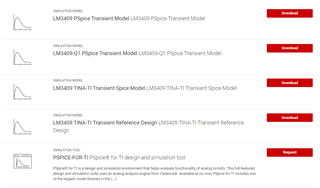
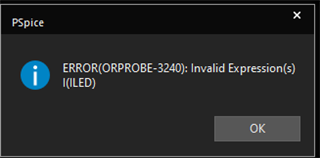
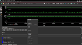
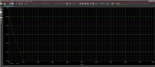
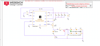
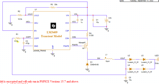
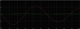
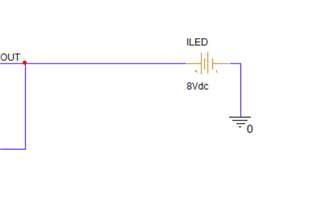
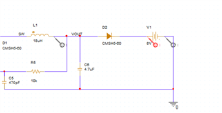
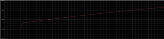
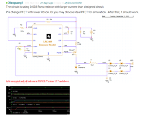
I am trying to simulate the LM3409 in Altium. It seems to be encrypted so I can not use it. TI got rid of their simulator and since then, I have not been able to simulate this design, which has been a big problem for me. Is there any way I can simulate this in Altium? Is there an unencrypted Pspice model that can be used in Altium? Is there a different software that you can recommend that will allow me to simulate this constant current LED driver?
Thank you
Hello Myles,
We have a model of the LM3409 in PSpice in the link below under Design Tools and Simulation.
LM3409 data sheet, product information and support | TI.com
Thanks Tuan
Hi Tuan,
I downloaded every one of those pSpice models and tried to get them to work. In Altium, it keeps saying that it is an encrypted model. Is there an unencrypted Pspice model that can be used in Altium? Is there a different software that you can recommend that will allow me to simulate this constant current LED driver?
Thanks,
Myles
Hello Myles,
These are different models in either PSpice or TINA simulations. These will not work in anything else but their designated soft-ware. We recommend you down load the PSpice soft-ware for the simulations in PSpice environment in the link below.
PSPICE-FOR-TI Simulation tool | TI.com
Thanks Tuan
Oh Great, I will try that. Do I just need to hit the request button and go from there?
Myles,
You will have to request it and please read and follow the Over-View on the link. It explains what you need to do.
Thanks Tuan
I got access to it and have tried to install it. Do you have directions on how to install it?
I am using the trans simulation settings that come with the lm3409 Pspice circuit that you can download. I am now getting this error message. I have tried to figure it out for a day now and cannot seem to get it to work.
I think the way it comes, it reads V(IN), V(SW), V(OUT), and I(LED).
I am trying to go into the simulation window to get rid of one of these traces but it will not let me because it cannot run.
If I add my own probes. The circuit works but then I get these two error messages.
Then I add a trace for the current through the LEDs and it does not work. says 0 amps. What other information can I provide for help on this?
Myles,
Not sure what you expected.
The ILED current is shown in the output window by default after you click Run Pspice. You can also right click mouse button in the output window, click "add trace" and add trace that you need to look into.
Yes, it runs with the setup when you first open the model, but I had to modify it in a few places and then change out the LEDs in order to get the correct forward voltage. Can I attach my project so you can see what I am talking about?
Yes, please.
Please provide more details. You may also attach video shot if needed.
So here is my schematic and what i get at the output. The current out of the inductor is actually great! I do not know why my LEDs are not reading anything.
I have attached my project. I just need any LED with about 3 forward Volts working to get this to work properly I believe.
Myles,
You are missing one resistor from Vout to Coff pin.
Please add the resistor and see if it works. If still not, please try changing R4 to 0.1ohm and see if it works.
I added a 10.2k ohm resistor. Seems like this just got me farther from I am going for.
I changed R4 to .1 and that choke down the amplitude of the sinusoidal wave to a max of 2A. That did not seem to work either.
The circuit is using 0.038 Rsns resistor with larger current than designed circuit.
Pls change PFET with lower Rdson. Or you may choose ideal PFET for simulation. After that, it should work.
I think that works with the LEDs that your schematic has, but becuase I am trying to simulate different LEDs with a high forward voltage, I will need the Rsns to be less to allow more current. Is that true or no?
When you selected 0.038ohm Rsns, you are targeting for design with IT-max = 6.5A.
To ensure IL(inductor current) can rise up to 6.5A and trigs PFET off, the voltage drop across Rdson and inductor resistor should be lower than Vin-VF, i.e:
Vin - 6.5A xRdson - 6.5A x RL > VF (1)
- VF : LED total forward voltage
- Rdson : Q1 Rdson
- RL : Inductor resistance
Or else, PFET will keep turning on and will never turn off.
The PFET(2N6845) in the schematic is 1ohm. You may reduce FET Rdson or select other PFET and make sure that Formula (1) meets the design.
Hope above explanation helps you.
So i changed my PFET to an ideal PFET and I believe my inductor is ideal as well. That would make Rdsn = 0 and RL =0 which would make equation (1) equal Vin > Vf, which is true in my case. 12V>5.8. I am still getting my most recent screenshot of simulation.
I wonder if it is a problem with the LEDs I loaded in from the TI 3rd party models? I believe I generated the part correctly and the LEDs are in a similar spec of what I wanted (around 3V).
I tried using a .1 ohm resistor, the simulation wouldn't run at all.
I checked the LED spec SML813WBC8W you are using, it's not recommended for new design. Further, it only delivers 20mA current. It's not suit for 6.5A application. You may simply replace LEDs with DC voltage.
However, I don't suggest relying on simulation result as the model is far different from real device. You may get one EVM board for real test.
My situation is interesting because this is a board our company already builds and sells and has done for a while. I am now trying to get the simulation to run to match how we have it running in real life. I added a voltage source to replicate the forward voltage of those 4 LEDs at 2.9 each. It gave me a weird graph.
I changed my pfet to a generic pspice component. Do you mean Square Wave waveform? I have to figure that out.
I have not been able to figure this out. Can you point me in a different direction or maybe there is something else we can try? Can you try to get the schematic working on your end with the LEDs having a forward voltage of 3V running at 2Amps?
Hi Myles – our experts for this issue are currently celebrating the Chinese Golden Week holiday, they will respond to you next week – Dave
Hi, Myles,
Actually, the schematic attached above already works, you can also find attached simulate result.