Other Parts Discussed in Thread: UC3854B, UC2854B
Hello all,
A long time ago: I asked a very similar question, at an earlier time in our project. At that time, we thought we resolved the issue, but turns out, it still needs improvement. See my previous question here:
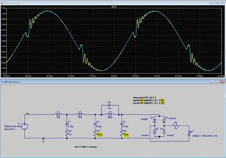
To summarize: We need to maintain low current distortion @ 400Hz, and when the input voltage is distorted according to my below screenshots.
Here is what has helped so far:
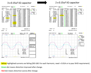
1. Reduce value of X-caps in EMI filter -- reduces the "transient response" effect (in the current waveform) at the "knee" of the clipped voltagewaveform.
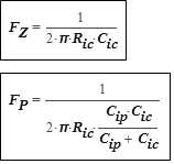
2. Increase ICOMP bandwidth, using lower value of. Here C(ICOMP) = 680pF ==> fc = ~15KHz according to the calculator
Here is what has not helped very much:
1. Changing switching frequency (tried +/- 20%, not much effect.)
2. Increase boost inductance to reduce DCM time (1200uH -> 1800uH -> 2500uH),
3. Change VCOMP network
The distortion is still too much.

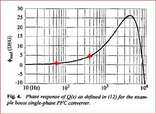
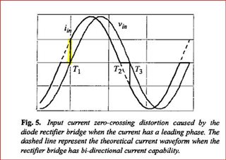
If you refer to these papers "On the Zero-Crossing Distortion in Single-Phase PFC Converter", Jian Sun, 2004 and "Demystifying Zero-Crossing Distortion in Single-phase PFC Converters", Jian Sun 2002, he shows that high current loop bandwidth alone cannot solve the zero-crossing distortion issue, but also requires the control loop to also be properly damped. I think he means, the phase margin of the control loop must be enough to prevent the control loop from oscillating as it transitions between DCM/non-conducting and CCM regions The 2002 paper clearly explains that a typical boost PFC stage has a leading current phase response, which worsens with higher line frequency. The issue is related to reverse biasing of the diode bridge which prevents the phase shifted PFC input current from pulling current continually throughout the cycle.
Many solutions have been suggested in various papers including:
1. Voltage (Vac) phase delay
2. Current reference (Iac) feed-forward
But UCC28180 is a highly integrated PFC controller and certain internal blocks cannot be externally accessed. Vac is not sensed directly, so it does not appear possible to apply a phase delay. to Vac And, feedforward of Iac does not seem possible. Other controllers, such as ISL6730A, *seem* to better consider this type of issue. (Untested, but demo board waiting)
If we stay with UCC28180, we believe our best option is to increase the bandwidth of the control loop and to improve the phase margin of the loop. This should damp the overshoot and ringing of the current waveform near the zero crossing.
But the UCC28180 calculator only suggests a Type-I compensation network (single ICOMP capacitor). In my previous thread, I asked for starting values for a Type-II ICOMP network, but those values did not really seem correct in our testing, and only made the distortion worse.
Its it possible for TI to modify the SLUC506 spreadsheet to include calculations for a Type-II compensator on ICOMP? Based on the information available in the datasheet, it is very difficult for us to do this ourselves. We also don't have enough experience to figure it out!
If you cannot modify the spreadsheet, can you help give us more clear equations on how to calculate the gain/phase response of the current loop with a Type-II network?
By the way, from SLUC506, what does a phase of -130° @ fc mean? I guess this is not the overall phase response of the current loop, just the current error amplifier?
Sorry for the long post. Thank you in advance,
Tim