This thread has been locked.

If you have a related question, please click the "Ask a related question" button in the top right corner. The newly created question will be automatically linked to this question.

TPS65988EVM: Dual sink functionality

Part Number: TPS65988EVM

Hi guys, 

Quite new to PD, looking for some help to setup the TPS65988EVM for my application.

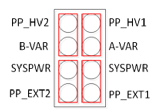
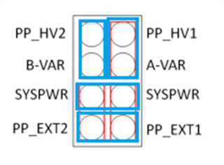
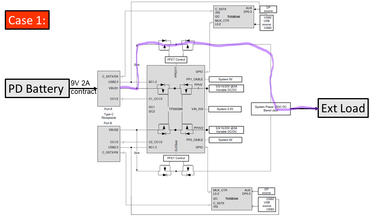
As shown in the attached diagram, I'm looking to use the 988EVM to power an electronic load dynamically from either type-C port.

Use cases:
1. A single PD compatible battery is plugged into type-C port A and negotiates a 9V 2A sink contract, the EVM is powered from this battery and can then source power from either the DC Barrel jack or one of the test points, to the external electronic load.

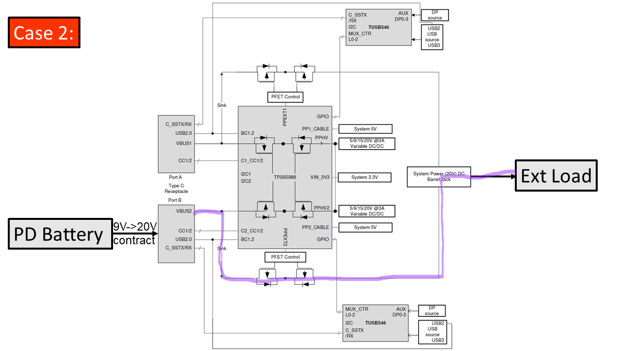
2. A single PD compatible battery is plugged into type-C port B and negotiates a variable sink contract 9V->20V, the EVM is powered from this battery and can then source power from either the DC Barrel jack or one of the test points, to the external electronic load.

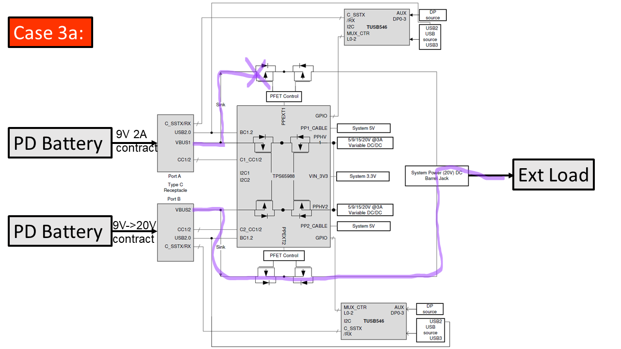
3a. With a single PD compatible battery is plugged into the EVM (either in port A or port B), a second battery is plugged into the spare type-C port, the EVM will prefer to negotiate a variable sink contract 9V->20V with port B. The EVM is battery powered and can then source power from either the DC Barrel jack or one of the test points, to the external electronic load.

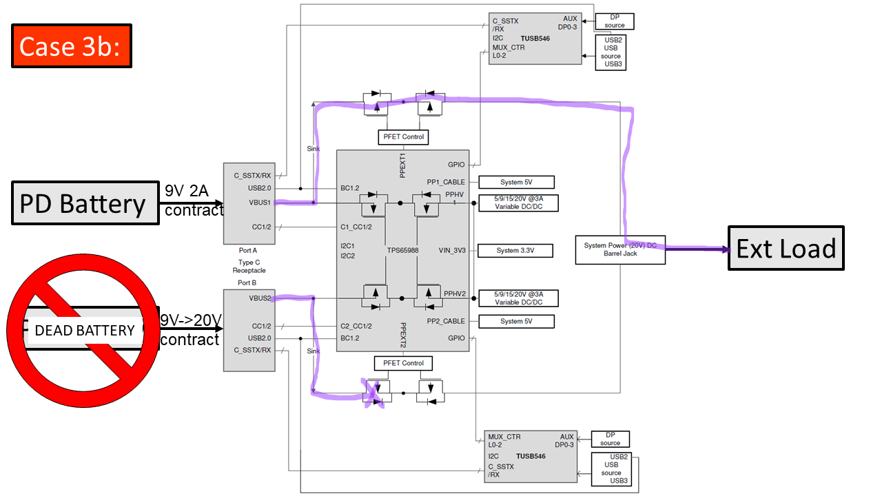
3b. Two PD compatible batteries are plugged into the EVM (one battery to port A, one battery to port B). The EVM prefers to negotiate a variable sink contract 9V->20V with port B, but if the battery plugged into port B dies or is disconnected, the EVM will switch to the connected port A battery. 
In both cases, the EVM is battery powered and can then source power from either the DC Barrel jack or one of the test points, to the external electronic load.

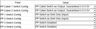
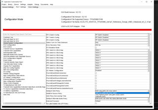
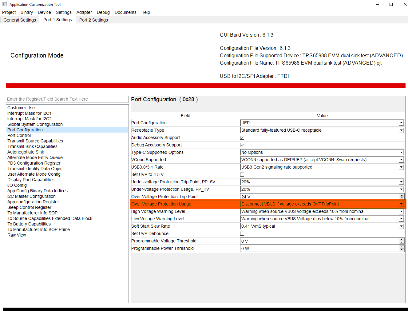
How would I go about configuring the device to achieve this? 

  • Hi Jack,

    I would recommend checking the tutorials found here, they should help with using the GUI configuration tool to configure the device. I will check internally about your questions related to the use cases and will get back to you tomorrow.

    Thanks and Regards,

    Chris

  • Hi Chris, 

    I have watched these, though I will watch again in case I missed something. 
    Excellent, looking forward to hearing from you. :) 
    Kind regards, 
    Jack. 

  • Hey Jack,

    I'm still checking on your question. I will try to get back to you by the end of the week.

    Thanks and Regards,

    Chris

  • Hi Chris, 

    Thanks for keeping me in the loop, appreciate it. :) 
    Looking forward to hearing from you. 

    Kind regards, 
    Jack.

  • Hi Jack,

    Thanks for your patience!

    We do not recommend using the barrel jack to source power in the configuration you want.

    Instead, we recommending moving the jumpers on J11 to short the external power paths(PP_EXT1, 2) directly and disconnect them from System Power.

    Default Jumper Configuration(Red)

    New Jumper Configuration(Blue)

    You can use the jumper shorting the PP_EXT pins as your test point for sourcing power.

    If you want to directly monitor the port states and control the power path PFETs, you would need an external MCU communicating with the PD controller.

    For your use case, you shouldn’t need to do this. If both External power paths are closed and both ports are sinking power, the reverse current protection circuitry will open the PFETs on whichever path is supplying a lower voltage (i.e. If the variable contract is sinking 15V and the fixed sinking 9V, the PFETs on the 9V power path will be turned off), so only one battery will be sourcing to the PP_EXT jumper at a time.


    In regards to your use cases, within the GUI, make sure to (1) configure both ports as Sinks only and (2) make sure the desired contracts are being advertised on each port (your fixed 9V 2A and your variable 9->20V).

    Thanks and Regards,

    Chris

  • e recommending moving the jumpers on J11 to short the external power paths(PP_EXT1, 2) directly and disconnect them from System

    Hi Chris,


    Thanks for getting back to me, and sorry for the delayed response.


    I followed your instruction, and the EVM almost behaves as intended:

    1. Using the RCP to open and PP switches works quite nicely! But only when going from a lower to higher-Wattage PDO.
      When I have both ports connected, and the higher-Wattage PDO battery is removed, the EVM drops, and must reboot before re-accepting the lower-Wattage PDO.
    2. You mentioned using the bridged PP_EXT1/2 jumper as a point of attachment for sourcing power to an external electronic load, though when either battery or both batteries are connected, no voltage is measured at PP_EXT1/2.
      Do I need to set the “PP 3-4 Switch Config” as a Sink/Source? (Didn’t want to perform without consulting you) Or did you instead mean attaching the external electronic load, to the bridged SYSPWR jumper?

    I’ve attached a zip file containing a video (in multiple formats), demonstrating the behaviour outlined in point “1.”.

    Kind regards,

    Jack.
    TPS65988 EVM dual sink test.pjtVBUS_DROP_VIDEO.zip

  • Hi Jack.

    Sorry about the delay,

    1. When the higher voltage PDO battery is removed, the voltage on the high voltage path is not discharged automatically. There may be a load transient from the higher-wattage side switch opening when the high-wattage battery is disconnected.

    Can you send scope captures of the voltages at Sys power and at the PP_EXT1/2 nodes during the event.

    But only when going from a lower to higher-Wattage PDO.

    Could you describe the steps taken when it works while going from lower to higher. I'm guessing that you only had the lower-Wattage battery connected, then connected the higher-wattage battery to the other port like in the second half of the video, but just wanted to confirm.

    2. I need to look into this one more and I'll get back to you about it.

    Thanks and regards,

    Chris

  • Hi Chris,


    1. From the capture included in the zipped folder I’ve attached; it doesn’t appear that this is an issue? No significant transient.
    2. Not a problem, looking forward to hearing from you.


    As a side note:
    I’ve noticed that when the 9V PDO is active on Port1, the PDO is disconnected after approximately 30s and doesn’t reconnect? It is my assumption that this just be an idle current draw timeout of the PD battery bank I’m using. Though I wanted to ask in case it’s a GUI setting somewhere.


    This dropping behavior is also visible on Port1’s VBUS TP while both batteries are connected, with the only difference being that the 9V PDO is renegotiated while the second battery is connected
    (1. It periodically drops in and out while the second battery is connected, and 2. drops out and never renegotiates the 9V PDO when only one battery is connected to Port1).

    P.S. For source devices, I’m using two of the following 20,000mAh PD battery banks.
    CYGNETT CHARGEUP PRO USB-C 20,000mAh USB-C Power Bank

    P.P.S

    Could you describe the steps taken when it works while going from lower to higher. I'm guessing that you only had the lower-Wattage battery connected, then connected the higher-wattage battery to the other port like in the second half of the video, but just wanted to confirm.

    Yes, you are correct.


    Kind regards,
    Jack.

    Hotswap Captures.zip

  • Hi Jack,

    Thank you for the scope captures.

    I looked over them with another engineer internally and we need to look further into the EVM layout on our side to figure out what is going on. There is a scheduled maintenance on the E2E site from today until October 2nd so will get back to you by next week after they finish maintenance.

    Thanks and Regards,

    Chris

  • Hi Chris,

    Not a worry; looking forward to hearing from you next week :) 

    Kind regards, 
    Jack.

  • Sounds good, Thanks Jack!

    BR,

    Chris

  • Hi Jack,

    Thanks for waiting!

    Using the RCP to open and PP switches works quite nicely! But only when going from a lower to higher-Wattage PDO.
    When I have both ports connected, and the higher-Wattage PDO battery is removed, the EVM drops, and must reboot before re-accepting the lower-Wattage PDO.

    Could you capture "Step 3: Disconnect second battery from Port2" again but with a longer sample interval. What's most likely happening is that the PD controller is losing power and shutting off due to insufficient supply voltage on its 3.3 V supply pin. The PD controller is powered from a buck converter that is sourced from the SYSPWR line. We want to see if the SYSPWR line drops from 15V to below ~5V which would shut of the PD controller.

    To avoid any rebooting, you want to be able to supply that P3V3 at all times.

    1. If the External load can supply power and hold the SYSPWR line high (ie. a battery) while the power paths are swapping, the PD controller should not reboot. If the load is passive and only sinks power, the PD controller will lose power and reboot (what you are currently seeing).

    2. On your own design, you can externally power the 3V3 line so that it is not affected by the SYSPWR

    I’ve noticed that when the 9V PDO is active on Port1, the PDO is disconnected after approximately 30s and doesn’t reconnect? It is my assumption that this just be an idle current draw timeout of the PD battery bank I’m using. Though I wanted to ask in case it’s a GUI setting somewhere.

    The PD controller shouldn't be turning off so it's mostly likely the idle current draw timeout you mentioned.

    You mentioned using the bridged PP_EXT1/2 jumper as a point of attachment for sourcing power to an external electronic load, though when either battery or both batteries are connected, no voltage is measured at PP_EXT1/2.
    Do I need to set the “PP 3-4 Switch Config” as a Sink/Source? (Didn’t want to perform without consulting you) Or did you instead mean attaching the external electronic load, to the bridged SYSPWR jumper?

    It looks like you are currently using the internal power paths as the sinks (opposed to the external power paths as shown in your diagram). The internal power paths support your current use cases, so unless you specifically need the external paths, you can stick with the configuration you are using. If you do want to use the external power paths, you would need to set the "PP 3-4 Switch Config" as Sink/Source like you mentioned and disable the internal power paths.

    Because you are currently using the internal power paths, we shouldn't see anything on the PP_EXT 1/2 Jumper.

    Thanks and Regards,

    Chris Lim

  • Hi Chris,

    Could you capture "Step 3: Disconnect second battery from Port2" again but with a longer sample interval.

    I’ve attached the requested extended capture of step:3 (as well as a copy of the debug log during the test), though I feel this is irrelevant;
    For the use case, the external electronic load should not lose power while there is at least 1 battery plugged. (The VBUS should swap to the remaining lower power PDO, before the SYS-PWR Bus has time to drop)

    When unplugging the higher power PDO battery, if the SYS-PWR Bus drops out it defeats the purpose of the battery “hot-swap” functionality.
    Ideally, the P3v3 rail (which is fed by the SYS-PWR Bus) shouldn’t require external supply, if the RCP resets fast enough.

    In the capture, the blue trace showing the SYS-PWR Bus voltage (with no load connected) is seen dropping to zero. Implying the RCP is not resetting after the higher power PDO battery is disconnected from the EVM.

    It looks like you are currently using the internal power paths as the sinks (opposed to the external power paths as shown in your diagram).

    Yes, I recently downloaded the Altium project for the TPS65988EVM which has made the routing much clearer to navigate.
    For now, the Internal power paths should be fine, unless otherwise required by the use case.

    Debug Log (14V5 to 9V).txt
    (1)Type-C(0x00):SNK_STATE_UNATTACHED_ACCESSORY(0x24)
    (1)Type-C(0x00):COMMON_STATE_UNATTACHED_SNK(0x66)
    (1)Type-C(0x00):SNK_STATE_UNATTACHED_ACCESSORY(0x24)
    (1)Type-C(0x00):COMMON_STATE_UNATTACHED_SNK(0x66)
    (1)Type-C(0x00):SNK_STATE_UNATTACHED_ACCESSORY(0x24)
    (1)Type-C(0x00):COMMON_STATE_UNATTACHED_SNK(0x66)
    (1)Type-C(0x00):SNK_STATE_UNATTACHED_ACCESSORY(0x24)
    (1)Type-C(0x00):COMMON_STATE_UNATTACHED_SNK(0x66)
    (1)Type-C(0x00):SNK_STATE_UNATTACHED_ACCESSORY(0x24)
    (1)Type-C(0x00):COMMON_STATE_UNATTACHED_SNK(0x66)
    (1)Type-C(0x00):SNK_STATE_UNATTACHED_ACCESSORY(0x24)
    (1)Type-C(0x00):COMMON_STATE_UNATTACHED_SNK(0x66)
    (1)Type-C(0x00):SNK_STATE_UNATTACHED_ACCESSORY(0x24)
    (1)Type-C(0x00):SNK_STATE_UNATTACHED_ACCESSORY(0x24)
    (1)Type-C(0x00):COMMON_STATE_UNATTACHED_SNK(0x66)
    (1)Type-C(0x00):SNK_STATE_UNATTACHED_ACCESSORY(0x24)
    (1)Type-C(0x00):COMMON_STATE_UNATTACHED_SNK(0x66)
    (1)Type-C(0x00):SNK_STATE_UNATTACHED_ACCESSORY(0x24)
    (1)Type-C(0x00):COMMON_STATE_UNATTACHED_SNK(0x66)
    (1)Type-C(0x00):SNK_STATE_UNATTACHED_ACCESSORY(0x24)
    (1)Type-C(0x00):COMMON_STATE_UNATTACHED_SNK(0x66)
    (1)Type-C(0x00):SNK_STATE_UNATTACHED_ACCESSORY(0x24)
    (1)Type-C(0x00):COMMON_STATE_UNATTACHED_SNK(0x66)
    (1)Type-C(0x00):SNK_STATE_UNATTACHED_ACCESSORY(0x24)
    (1)Type-C(0x00):COMMON_STATE_UNATTACHED_SNK(0x66)
    (1)Type-C(0x00):SNK_STATE_UNATTACHED_ACCESSORY(0x24)
    (0)INT(0x05):READY_FOR_PATCH(0x51)
    (0)PD(0x04):PEState_CableTypeDetect(0x01)
    (0)Type-C(0x00):COMMON_STATE_UNATTACHED_SNK(0x66)
    (1)PD(0x04):PEState_CableTypeDetect(0x01)
    (1)Type-C(0x00):COMMON_STATE_UNATTACHED_SNK(0x66)
    (0)Type-C(0x00):COMMON_STATE_ATTACHWAIT_SNK(0x65)
    (0)Type-C(0x00):COMMON_STATE_ATTACHED_SNK(0x61)
    (0)INT(0x05):READY_FOR_PATCH(0x51)
    (0)PD(0x04):PEState_CableTypeDetect(0x01)
    (0)Type-C(0x00):COMMON_STATE_UNATTACHED_SNK(0x66)
    (0)INT(0x05):READY_FOR_PATCH(0x51)
    (0)PD(0x04):PEState_CableTypeDetect(0x01)
    (0)Type-C(0x00):COMMON_STATE_UNATTACHED_SNK(0x66)
    (1)PD(0x04):PEState_CableTypeDetect(0x01)
    (1)Type-C(0x00):COMMON_STATE_UNATTACHED_SNK(0x66)
    (0)Type-C(0x00):COMMON_STATE_ATTACHWAIT_SNK(0x65)
    (0)Type-C(0x00):COMMON_STATE_ATTACHED_SNK(0x61)
    (1)PD(0x04):PEState_CableTypeDetect(0x01)
    (1)Type-C(0x00):COMMON_STATE_UNATTACHED_SNK(0x66)
    (0)Type-C(0x00):COMMON_STATE_ATTACHWAIT_SNK(0x65)
    (0)Type-C(0x00):COMMON_STATE_ATTACHED_SNK(0x61)
    
    Extended STEP3 Test Proceedure.pptx

    Kind regards, 
    Jack.

  • Hi Jack,

    Thanks for sending over the scope captures, we just wanted to verify what was happening on the bus voltages. I am checking things over internally and will get back to you by next Monday.

  • Hi Jack,

    Can you see what setting you have "Multiport Sink Policy" set to? If not already, try setting it to "Both sink paths will close switch". The setting should be under: Global System Configuration -> Multiport Sink Policy

    Thanks and Regards,

    Chris Lim

  • Hi Chris, 

    Yes, this is the "Multiport Sink Policy" setting that I've been using by default. Though, I've also tried the "Only the highest power sink path closes switch" option with no difference in performance.

    I just noticed from you attached image, that you have a far newer release of the GUI (6.2.12 > 6.1.3); could I get my hands on that version/would that be useful in this situation? 

    One last question, have you been able to successfully prototype this dual sink functionality on your end? Is this issue exclusive to my EVM?


    Kind regards, 
    Jack. 

  • Hi Chris, 

    I appears I've just cracked it!; two things:
    1 - Started an "Advance template" and set it up as per normal. After re-reading the TRM, I thought perhaps the OVP may've had something to do with keeping the remaining (in this case, lower power) PDO on Port-A open. So, I set it to "Disconnect VBUS if voltage exceeds OVPTripPoint". 
    This alone didn't solve the issue as it still dropped going from high to low, however the SYSPWR bus did stay up for approximately 1/2second before rebooting the device.


    2 - I was poking around in the debug registers when I noticed that after clearing the "DBfg" (Dead Battery Flag Clear), the EVM no longer rebooted!!!! 


    I've included a video of the hot-swap application working. 


    Thank you for all your help so far; the only other question I have now is how to clear the [DBfg] automatically?

    Best regards, 
    Jack.

  • Hi Jack,

    I'm glad that you were able to figure out a solution.

    Unfortunately, there is no way to automatically send the DBFG command with only the EVM. You would need to send the command over I2C. That also would be the only way to clear the Dead battery flag.

    I just noticed from you attached image, that you have a far newer release of the GUI (6.2.12 > 6.1.3); could I get my hands on that version/would that be useful in this situation?

    The newer version of the GUI supports a different part in the same family. Using the 6.2.12 Gui may cause issues with the 988.

    Thanks and Regards,

    Chris

  • Hi Chris, 


    Unfortunately, there is no way to automatically send the DBFG command with only the EVM. You would need to send the command over I2C. That also would be the only way to clear the Dead battery flag.

    I have successfully automatically sent the DBFG command with only the EVM, though use of the GUI's "Configuration Sets".
    I've attached a PDF document outlining the EVM setup as well as the project file, in case anybody comes looking here for the solution in the future. 

    I'm moving this case to resolved, thank you for your patience and help with this.


    Kind regards, 
    Jack.


    Automated Battery hot swap configuration [1].pdf
    [AUTO Clear DBfg] TPS65988 EVM dual sink test (ADVANCED).pjt

  • Hi Jack,

    I'm glad you were able to figure out a solution the the battery hot swap.

    Thanks and Regards,

    Chris