This thread has been locked.
If you have a related question, please click the "Ask a related question" button in the top right corner. The newly created question will be automatically linked to this question.
Hi Team,
I have used LLC IC UCC256404 for 18V and 500W LLC converter design.
I am facing load regulation issue means at no load output 18V coming properly and when I am applying load 1A then output voltage continuously goes up and down at every 12ms. I have check all the parts as well as replaced some components like Opto-isolator and TL431. But problem have not resolved.
For Boost PFC used IC UCC28180. The PFC section found ok. I have tested PFC section separately.
Can you please share your suggestions and feedback.
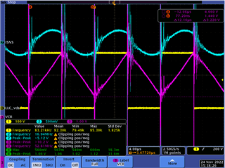
I have check waveforms at ISENSE, BW, VCR and FB pins.
As per my understanding it detect overcurrent protection fault. Is it the transformer issue?
email-id- rajkumar.chaurasiya@emerson.com
Hi Team,
I have another question.
Can we use UCC256404 for 600KHz switching frequency with GaN FETs?
Hello Rajkumar,
Due to the shortened Thanksgiving week here in the US, our product expert won't be available until next week. In the meantime, please provide a schematic as well as the waveforms you've collected so he can provide meaningful feedback.
Thank you for your patience.
Ray
Hi Ray,
Thanks for sharing.
Actually we have build two protos. Previously both are working fine but during the Conducted emission testing one board got damaged. Then I have trying to debug but issue not resolved.
No issue in the schematic.
After damaged the board some fault detect in the board. The output voltage continuously goes up and down at every 12ms. RVCC also continuously goes up and down and frequency limit at load that why voltage regulation issue.
Please suggest me your input and check points.
Thanks,
Hello Rajkumar,
It sounds like the board may be going into OVP protection. I would check your feedback circuit to see if it has been damaged some how.
Regards,
Hi,
Thanks for sharing the suggestions.
I wanted to know. what will I check in feedback circuits?
I have checked optocoupler and TL431 and also replaced both the parts.
I have selected resistor divider upper side 6.2K and 68K both are in series and lower side 12K.
Still not in working.
1- FB Pin waveform
2- RVCC with Load
3- VCC with load
4- HV Pin
5- FB Pin 2nd waveform
Please let me know if you need other pins waveform.
Thanks,
Hello,
You had mentioned that the device got damaged during conducted admission testing during trouble shooting.
I had thought that maybe the TL431 feedback circuitry. Since you changed the components on the TL431 circuit and the issue does not go away, this circuity most likely is not damaged. However, you might want to double check it's functionality with separate bias supplies without power applied to make sure it functions correctly.
From your waveforms VCC is cycling between VCCSTARTSELF (26V) and VCCReStartJFet (9.65V).
The FB pin starts from zero and soft starts to 5.6V and then shuts down.
This could indicate an over voltage fault, over current fault or damage UCC256404 bias supply.
Since your design was working you may have damaged the H Bridge FETs, ISNS resistor capacitors even the VCR divider capacitors.
You may want to check them to see if they are O.K.
You might want to see if the bias supply got damaged. The auxiliary diode and/or VCC capacitors could be damaged.
Regards,
Hi,
Thanks for sharing the suggestions.
I wanted to know. what will I check in feedback circuits?
I have checked optocoupler and TL431 and also replaced both the parts.
I have selected resistor divider upper side 6.2K and 68K both are in series and lower side 12K.
Still not in working.
1- FB Pin waveform
2- RVCC with Load
3- VCC with load
4- HV Pin
5- FB Pin 2nd waveform
Please let me know if you need other pins waveform.
Thanks,
Hi team,
Thanks for your suggestions.
Issue has been resolved and board is working fine. Actually auxiliary supply not was not working properly. Mainly the issue was in auxiliary supply.
I have capture some waveforms like VCR , ISNS, BW, FB and Low side MOSFET Vds at 110VAC with different loads .
Waveforms picks lots of noise and peaks goes very high.
Please suggest how to overcome these noise.
I have attached the waveforms.
1- Blue- BW Pin
Yellow- LO Pin
2- Purple- FB pin
Yellow- LO pin
3- Blue-ISNS Pin
Purple- VCR
Yellow- LO
4- Purple- RVCC pin
Blue- ISNS pin
Yellow- LO pin
5- Blue- ISNS
Purple- VCR
Yellow- LO
6- UCC256404 LLC Schematic
Thanks for your suggestions.
Thanks & Regards,
Rajkumar Chaurasiya
Hi Rajkumar,
All the switching frequency noise that you see is due to not following the proper probing.
Please measure these signals by making probe ground loop small as shown in the below picture (refer: Power Tip #6: Accurately Measuring Power Supply Ripple - EE Times).
Regards
Manikanta P