Hi Team,
I have a question about VDD1 Output Current and divider resistance, could you kindly ask below questions:
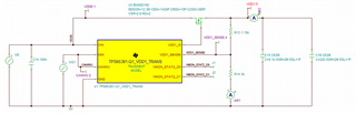
- What's 'IVDD1 Minimum current realized with external resistive divider' mean? 10mA current will limit what configuration? When should we consider 10mA minimum current?

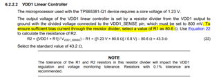
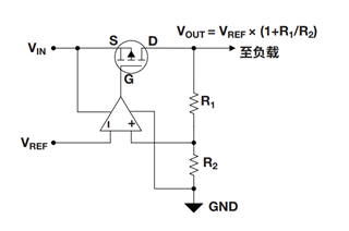
- Why VDD1_SENSE pin must to be set to 800mV? Why we need sufficient current? Is 80.6 resistance is a fixed value? Can I choose other value like 3k?
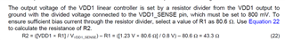
I don't know why this picture is so flurry, you can find this in page 11 and 97 of TPS65381A datasheet.
Thanks
BRs
Kian