A related question is a question created from another question. When the related question is created, it will be automatically linked to the original question.
If you have a related question, please click the "Ask a related question" button in the top right corner. The newly created question will be automatically linked to this question.
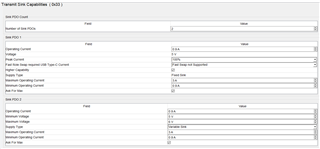
Let me test this out from my end, can you try testing out fo9rm your end if GPIO 14 and GPIO 15 respond correctly if there's only one sink PDO in your configuration.
To clarify, test to ensure if GPIO 14 and GPIO 15 both respond when there's only a Sink PDO of 5V/1.5A and only a sink PDO of 5V/3A.
BTW, I'm using the Evaluation Board TPS65987EVM boards (together with your 10G-Expansion EVM boards) for evaluation in order to rule out any hardware issue in my own design.
Before we went on break, we were able to replicate your issue on our end and were working on debugging it. I'll need to verify this with a team member and re run the test, but it appeared like the gpio events were working properly and we would never enter the 2nd PDO that corresponded to GPIO 15. Let me verify the findings this week and get back to you.
I have not seen configurations with multiple PDOs at the same voltage, so there may be a chance we do not support this.
Your original question appeared to be if there was any way to differentiate between a 5V/1.5A and 5V/3A Source capability. This would require more complexity in hardware and software, but you should be able to read register 0x30(received source capabilities) over I2C from our device. We would return the raw binary values and you could decode those, similar to how we read them through the GUI.
I will continue to look at the GPIO event and try to get back to you by the end of the week.
I read over the initial thread again and saw that the core question was "Is there a way to differentiate between 5V/1.5A and 5V/3A source capabilities". If you are comfortable with I2C, you can read the Source capabilities and Active PDO registers from the PD over I2C, and decode the values to see what Source capabilities are being offered and the current PDO. Information on the formatting is found in the TRM, and the formatting of the PDOs can be found in section 6.4 of the USB-PD specification.
In regards to the current solution with the GPIO's:
The GPIO events appear to be working correctly. My initial thoughts are that we do not support same voltage PDOs. It seems like PDO1 is always chosen, which is why we only see the GPIO associated with it lighting up. I'll still look into contacting someone who may be able to provide more insight into this problem though.
I brought up your issue to one of the more experienced engineers on the team today and may have a solution to your answer.
1. You can not have fixed voltage PDOs with the same voltage (this is according to the USB-C PD spec)
This explains why we do not support, and cannot get the PD to choose the secondary 5V Sink PDOs.
Solutions
1.
A potential workaround is to make the first PDO a fixed 5V 1.5A contract (the first contract must be a 5V fixed), and make the second a variable contract from 5V to (value greater than 5V. ie. 6 or 7). This should trigger the GPIO events properly, but you may risk getting into a weird voltage contract if a source can provide a contract in that range.
2.
The only other option for obtaining source caps is reading the registers over I2c that I mentioned in the previous reply.