This thread has been locked.
If you have a related question, please click the "Ask a related question" button in the top right corner. The newly created question will be automatically linked to this question.
Hi,
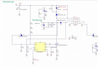
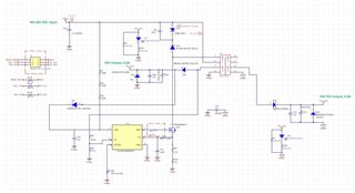
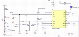
We are producing the custom board(28704) as follows.
R116, R138, FET(Q14), R89, R137 are burned in a few boards.
we are using the 15V_aux power for the ucc 256303 and using the 15V_ISO power for the UCC24612-2
can you help me?
Regards,
Nick
Hi Seongwoong,
Thanks for reaching out! Can you check/provide the power ratings of the resistors that are burnt? At first look, I would recommend putting the two current sense resistors in parallel (R89 and R137) to have current be distributed among them so the resistors have less stress, but there may be more to debug this issue.
Can you provide the power ratings of the passive components?
the size of the resistor 3216 is 0.5W
after power on, the resistors are not burnt.
If all of the boards are burnt, that's right. The resistors burnt occurred on a few boards after several months
another reason..?
Thanks
Regards,
Nick.
Hi Seongwoong,
I am assuming that it is the burnt FET that leads to other resistors to fail. Can you check the FET's drain voltage and source voltage at full load to see if it is operating correctly?
Thanks,
Claire
Hi Claire,
Gate dampling resistor is 47 ohms. Is it fine?
I think the resistor is big?
Thanks,
Nick
Hi Seongwoong,
The series gate resistor functions for reducing ringing and control turn on time for FET.
The following app note provides details on the choice of gate drive resistor.
I think 47-Ohm resistor should be fine. If the FET turns out to switch faster than you would like, increase the resistor value (less current flows in the gate to charge the FET). If the FET switches slower than you would like, decrease the resistor value (10-Ohm) for more current flowing into gate.
Hi Nick,
If there are no further questions, I will close this thread.
Best,
Claire