Because of the holidays, TI E2E™ design support forum responses will be delayed from Dec. 25 through Jan. 2. Thank you for your patience.

This thread has been locked.

If you have a related question, please click the "Ask a related question" button in the top right corner. The newly created question will be automatically linked to this question.

UCC28180: UCC28180 PFC and THD issue

Part Number: UCC28180
Other Parts Discussed in Thread: PMP40766, TIDA-01494, UCC256404

Hi TI team,

I have used PFC Boost Converter IC UCC28180 with boost PFC + LLC Converter. PFC power supply Output voltage 390VDC, main LLC output is 18V and output power 500W.

I am facing issue of Power factor correction as well as THD problems.

In input AC current waveform lost of noise. Input AC current not follow the input voltage. 

I have try to resolve the issue with the pin 2 ( ICOMP pin) of UCC28180 by changing the capacitors values  for current compensation. But no changed in the input current waveforms.

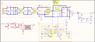
I have share the waveforms and schematic. 

Can I tune the voltage compensations VCOMP pin or 

Please your suggestions and feedback.

email-id- rajkumar.chaurasiya@emerson.com

Schematic

Input Current Waveform with AC power source

Input Current Waveform at 110VAC

Input Current Waveform at 230VAC

Input Current wavform

Blue- Input AC Current

Yellow- Rectifier output voltage

Blue- Input AC Current

Yellow- Rectifier output voltage

Blue- Input AC Current

Yellow- VDS

Blue- Input AC Current

Yellow- VDS

  • Hi Please find excel sheet calculations. I will request that please and update.

    Switching Frequency 100KHz

    Boost Inductor Value 416uH.20V 25A_PS_ETC.xls

  • Blue- AC Input current 

    Yellow- VDS 

    I have tested with 10mOhm current sense resistor also. But no improvement.

    I have also changed the Voltage compensation RC network VCOMP Pin5 with 3.2K and 4.7uF.But no improvement here also.

    Please suggest.

    Thanks 

  • Input Current - Blue 

    Input Voltage - Yellow

    at 110AC power source with 23.5mOhm current sense resistor 

    Input Current - Blue 

    Input Voltage - Yellow

    at 230VAC with 23.5mOhm current sense resistor 

  • Hi Rajkumar, 

    Thank you for the query on UCC28180. We will look into the waveforms and come back to you.

    Regards,

    Harish

  • Hi Rajkumar,

    Going through your system specifications of 500W, I see it is very similar to the designs PMP40766 and TIDA-01494. So you inducto of 410uH and sense resistor close to 20mohms is fine and I don't think you will need to tune this further.

    The voltage loop could still be improved, I suggest checking the above designs for the value compensation resistors and capacitors and see if this helps. I still feel this might not be addressing the actual issue.

    First, What is the value of bulk capacitor after the diode bridge rectifier? I recommend reducing this capacitor value to minimum (0.33uF) to see if this helps in addressing any residual voltage across bulk cap which might prevent diodes from providing current at zero crossings.

    Second, At the zero crossings the voltage across the inductor is very low and so the converter is unable to deliver the required current and could probably lead to current amp saturating. The current recovers when the amplifier comes out of saturation. Can you please check if the amplifier is saturating or not?

    Regards,

    Harish

  • Hi Harish,

    Thanks for the suggestions. 

    I will try to tune the voltage compensations. Can you suggest which value I can use for voltage compensation R13, C14 and C13? 

    1. The value of bulk capacitor is 270uF/450V. Sure I will reduce the capacitor value. Please see the below image.

     2. Yes ....

    Second, At the zero crossings the voltage across the inductor is very low and so the converter is unable to deliver the required current and could probably lead to current amp saturating. The current recovers when the amplifier comes out of saturation. Can you please check if the amplifier is saturating or not?

    Can you please let me which pin need to monitor for current amplifier saturation and how to check? What is the saturation limit of the current amplifier.

    I have done lot of activity for tuning the VCOMP pin, ICOMP pin, ISENSE RC Capacitor and also changed current sense resistor with 10mOhm and 23.5mOhm. But nothing change in the current shape.

    I will try again to turn VCOMP pin.

    Please provide your suggestions.

    And I will request please provide your suggestion today then tomorrow I will do some experiment.

    Thanks & Regard, 

    Rajkumar Churasiya

  • Hi Rajkumar,

    I meant the voltage at ICOMP pin. The DC side capacitor is fine. I had a doubt on the bulk capacitor after the diode rectifier which could potentially have some residual voltage causing this distortion.

    Please let me know if you can verify this.

    Thank you

    Regards,

    Harish

  • Hi Harish,

    I have checked the voltage after diode rectifier. There is no residual Voltage.

    See the below image.

    Yellow- Rectifier DC Voltage 

    Blue - Input Current

    Today I have performed some experiment by turning the VCOMP pin RC network.

    I got some better result as compare to the previous.

    Yellow - Input AC Voltage 

    Blue - Input AC current.

    Please provide your suggestions.

    Thanks 

    Rajkumar

  • Hi Rajkumar,

    It seems there is a slight phase shift in the current signal. Can you try reducing C5 to 0.1uF/0.22uF and see if this helps?

    Thank you

    Regards,

    Harish

  • Hi Harish,

    Thanks for your suggestions.

    Sure I will do.

    I have another query.

    Today I have tested PFC only means disable the LLC controller UCC256404.

    The input current shape is also not good. Please see the below image.

    Please provide your suggestions and feedback.

    Thanks  

  • Hi Harish, 

    Why the PFC not working in UCC28180 IC?

  • Hi Rajkumar,

    There seems to be no PFC action here. I am not sure what changes have been made, disconnecting the LLC should not affect PFC stage performance. You might check for any damage which could have caused failure.

    Regards,

    Harish

  • Hi Harish,

    I have shorted BLK Pin 4 of the UCC256404DDBR and provide 12VDC external supply across C16 for UCC28180 VCC supply. I have done testing with 400 Ohm resistive load.

    I have checked everything is working fine and also replaced UCC28180 with new.

    When I connect the load across LLC output the get current phase shift.

    Please see below image.

    As per my calculation the current resistor should be 24mOhm. Any problem with this?

    Vin_min 85 VAC
    Vin_nom 110 VAC
    Vin_max 265 VAC
    120.2081528 VDC
    155.5634919 VDC
    374.766594 VDC
    fLine_min 47 Hz
    fLine_nom 50 Hz
    fLine_max 63 Hz
    Vout_min 380 V
    Vout_nom 390 V
    Vout_max 410 V
    Pout 500 W
    Iout 1.282051282 Iout
    Fsw 104 KHz
    Effi 0.94
    PF 0.99
    Worst Case Duty Cycle (D)   0.5
    Iout_max 1.282051282
    Iin_RMS 6.321032604
    Iin_max 8.939290037
    Iin_avg 5.69200257
    Delta I_ripple 0.4
    I_ripple 3.575716015
    Delta V_rippl 0.07
    Vin_ripple 8.414570696
    Cin=I_ripple/(8*Fsw*Vin_ripple) 0.000510749
    0.510749241 uF
    Cout 270 uF
    IL_peak=Iin_max+(I_ripple/2) 10.72714804
    L_min=(Vout*D*(1-D))/(Fsw*I_ripple) 0.262185251
    262.1852508 uH
    L_act 410
    I_ripple(act) 0.002286585
    2.286585366 A
    IL_peak(act) 10.08258272 A
    D_max=Vout-Vin_min(RECT)/Vout 0.691773967
    Rsense=VSOC(min)/IL_peak(act)*1.1 0.023352602
    23.3526024 mOhm
    0.024 Ohm

    Input voltage 110V with 10A Load current


    Input voltage 230VAC with 15A Load current

    Input voltage 110V with 10A Load current at zero crossing

    Input voltage 2300V with 10A Load current at zero crossing

    Please provide your suggestions & feedback.

    Thanks

  • Hi Harish,

    One more thing, when I apply the 400 Ohm resistive load (1.25A) across the PFC output i.e. 390V. The PFC function continuously not working I mean some time PFC function is in working and some time not in working.

    I do not know why is it happing. But I have doubt on the current sense resistor.

    Please see the below image.

    Sometime coming Non PFC current waveform like Blue color and sometime coming PFC current waveform like green color at fixed time interval.

    At 1.25A load current waveform should be like green color. right?

    I will share the capture waveform as soon as possible.

    Thanks 

  • Hi Rajkumar,

    I feel current sense resistor close to 20mohm should be fine. (you might consider reducing 24mohm value)  So can I assume now that UCC28180 working fine as standalone without LLC, bu when LLC stage is connected there seems to be a phase shift, or do you have this behaviour with PFC standalone?

    Also, for the intermittent operation of PFC, is the Vcc supply stable or you are supplying from aux windingof the LLC stage?

    Please let me know your test conditions for above.

    Thank you 

    Regards,

    Harish