Other Parts Discussed in Thread: BQ76952
Hi all,
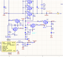
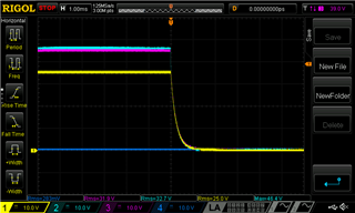
I have noticed that the BQ76200 in combination with the mosfets i'm using turn off very slow. I think this is due to the fact that the Vgs(th) of my mosfets are between 1,2 and 2V. Which is very low.
The turn off time looks very similar to this post: https://e2e.ti.com/support/power-management-group/power-management/f/power-management-forum/797982/bq76200-turn-on-off-timing-improvements-for-gate-drive-short-circuit-protection-failure?ReplyFilter=Answers&ReplySortBy=Answers&ReplySortOrder=Descendin
Because of that my mosfets fail during a short circuit (SOA curve can't handle the slow turn off time).
As i can see in that post, he starts to use a PNP solution by someone of TI's recommendation (https://www.ti.com/lit/ml/slua618a/slua618a.pdf?ts=1671075384344&ref_url=https%253A%252F%252Fwww.google.ca%252F)
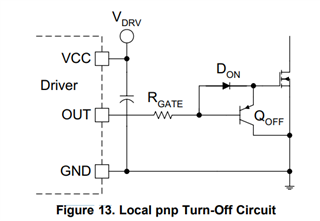
Would it be possbile to replace the Qoff (pnp) transistor with a P-mosfet, or has this more disadvantges? And to avoid a large inductive spike, would it be possible to put resistor in series with the transistor to regulate the turn off time?
Best regards,
Jan