This thread has been locked.

If you have a related question, please click the "Ask a related question" button in the top right corner. The newly created question will be automatically linked to this question.

UCC2895: Could I have an unencrypted SPICE model for UCC2895/UCC3895?

Part Number: UCC2895
Other Parts Discussed in Thread: UCC3895,

Hi,sir or madam​

I need to use UCC2895/UCC3895 for simulation, but only the encrypted spice model is available on the TI official website. Could I have an unencrypted SPICE model for UCC2895/UCC3895?


Best regards,​

​Jixiang Song

  • Hello,

    I am looking into you inquiry and will get back to you shortly?

    Regards,

  • Hello,

    I found this file in the repository.  Please give it a try.

    uccx895-master@b5c0038ff22 (3).zip

    Regards,

  • Thank you for providing me with the unencrypted model. After using the model you provided, the simulation can be run, but after testing, the PWM output ports OUTA~OUTD are always high level or always low level or irregular duty ratio. I don't know whether there is a problem with my setting or the model is inaccurate.

    Best regards,

  • Hello,

    Some times models will give arounenouse answers if you are not taking enough samples.  Try increasing your sample size to see if the issue goes away.

    The other issue might be with the simulation software that you imported the encrypted model too.  You also might want to try using the TI Pspice for simulations to see if the issue goes away as well.

    Regards,

  • Thanks for your reply! 
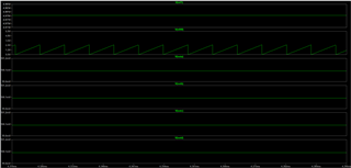
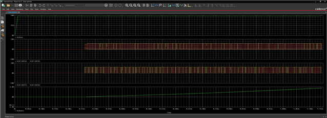
    Firstly, I don't understand what you mean by increasing the sample size. I have provided the schematic and part of the waveforms below. The reference voltage on pin 4 and the sawtooth wave on pin 7 are normal, but OUTA~OUTD are 100mv DC level. Why is that?
    Secondly, the model I used was TI Pspice, and its path is “uccx895-master@b5c0038ff22 (3)\UCCx895-TI\Development-PSPICE\PSPICE\UCCx895_PSPICE_TRANS\From_Local_Work_Folder\UCC3895_PSpice Version 2 with new libraries from Danny/Copy of ucc3895”, because it's the only one that's unencrypted.

    Excuse my poor English and looking forward to your reply.
    Best regards,

  • Hello,

    I am reviewing you inquiry and will get back to you shortly.

    Regards,

  • Hello,

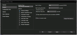
    In regards to the sample size it has to due with step size.  The smaller the maximum step size the more sample points are taken.  You can can fin this setting in the sample settings.

    My questions was in regards to the simulation tool you were using, not the model that I had given you.  We have TI PSpice simulator which you can down load for free. I thought part of the error you were seeing was do to the simulation tool that you were using and not a model issue.

    Regards,

  • Hello Mike,
    Thank you again for your reply.
    I tried to reduce the simulation time step, but the problem was not solved. 
    The simulation software I use is LTspice. I have used Pspice model provided by TI in this software before and it can run normally, but this time is different from before. Do you know if the pspice model is fully applicable to LTspice? And is there a way to solve this problem without replacing the simulation software?
    Best regards,

  • Hello,

    If you need support with LT Spice you will have to contact Analog device support.

    In regards to your simulation you may try running the released  model in TI PSpice to see if your simulation results are more of what you expect.

    Regards, 

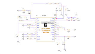
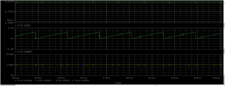
  • I downloaded TIspice and found the UCCx895 model in its own device library. But the results were still disappointing.  As I described earlier, the reference voltage on pin 4 and the sawtooth wave on pin 7 are normal, but OUTA~OUTD are 100mv DC. Is there any mistake in my peripheral circuit design? I have provided the schematic and part of the waveforms below. Looking forward to your reply.
    Wishing you and yours a very happy Christmas!
    Best regards,

  • Hello,

    I am reviewing your inquiry and will get back to shortly.

    Regards,

  • Hello,

    I ran the transient PSpice model on the web and it is functioning correctly.  https://www.ti.com/lit/zip/slum055

    I would start with the working model that is on the web and make modifications based on your design.  It will make the debugging process easier. 

    https://www.ti.com/lit/zip/slum055

    Regards,

  • Hello,
    Could you please send me the schematic you built? I don't know why it went wrong.
    Best regard,

  • Hello,

    The schematic in the model is unmodified and you should be able to run it from the TI PSpice tool directly.  You can find the model at the below link. 

    https://www.ti.com/lit/zip/slum055

    Regards,

  • Hello,
    I learned from the data sheet of ucc3895 that ucc3895 can work in current mode or voltage mode. In current mode, the RAMP pin is connected to the CS pin. And in voltage mode, The RAMP pin is connected to the signal at CT. I want ucc3895 to work in voltage mode, but the case in TI PSpice tool is current mode. I'm not sure if the circuit I've built will allow ucc3895 to work properly in voltage mode, and I think that's where the problem lies. Could you please help me check the circuit I sent above or provide me with a voltage mode case?
    Best regards,

  • Hello,

    I am reviewing you inquiry and will get back to you shortly.

    Regards,

  • Hello,

    I prefer designing phase shifted full bridge designs in peak current mode control vs voltage mode control.  This helps prevent transformer saturation, protects the H Bridge from over current and eliminates the need for a DC blocking capacitor in series with the input of the transformer. 

    However, if you should be able to modify the model to use it in voltage mode control by developing the RAMP off of CT and adding a DC blocking capacitor to the input of the transformer.

    Regards,