In which direction is the hysteresis voltage applied?
Based on Figure 8-2 (attached) of the from the TL7700-SEP datasheet (SLVSF13A Rev August 2021), it appears that Vhys is applied on the upward edge of the SENSE input. I.e., when the SENSE voltage is rising, RESET stays asserted until VCC > Vs' + Vhys. When SENSE voltage is decreasing, RESET will assert when Vcc < Vs'.
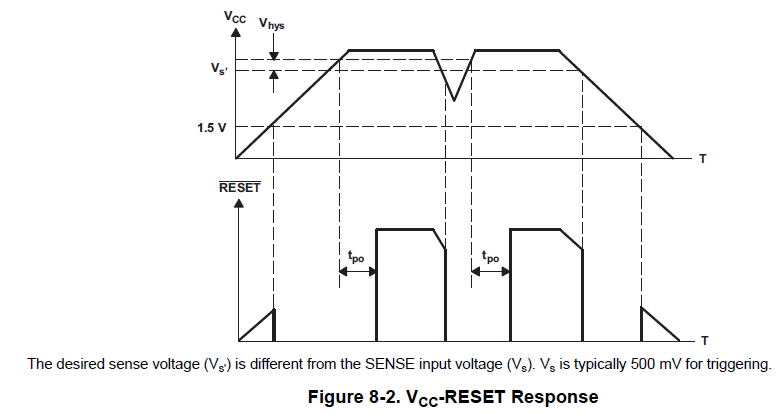
If the above statements are true, then the design example shown in the Typical Application section will not work. The example has the following parameters:
Voltage supply: Vcc = 5V
Desired sense voltage: Vs' = 4.5V
Hysteresis voltage: Vhys = 0.6V.
If Vcc must go above Vs' + Vhys (4.5V + 0.6V = 5.1V) to release the reset, then RESET will always stay asserted because Vcc will only reach 5V max.
In order to properly design my system, please tell me which of the following are incorrect:
1. Figure 8-2
2. The example application
3. My interpretation of the datasheet.
Thank you,
Will